1
2
QL1
QL2
A00
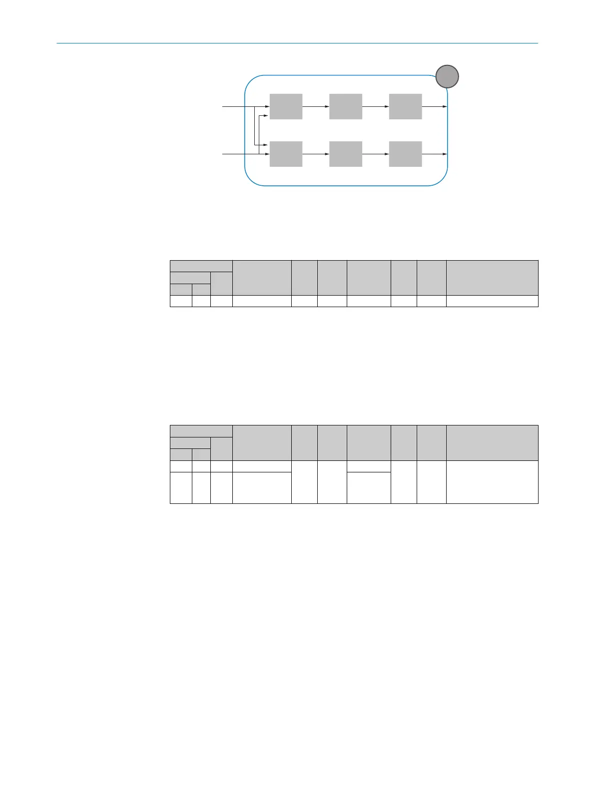
Logic 1 Timer 1 Inverter 1
Logic 2 Timer 2 Inverter 2
Figure 24: Logical principle of operation A00
1
Diagnostic alarm or external input
2
Diagnostic alarm or external input
Table 15: Smart Tasks - SLTI Version
ISDU
Name
Data
type
Data
storage
Length Access
Default
value
Value/RangeIndex
Subin‐
dex
DEC HEX
1080
438 - SLTI version String - 8 byte ro - -
The SLTI version contains the version number for the Smart Task basic logic.
The selection of the desired input signals for the Smart Task basic logic is made for
the first input via Index 1081 and for the second input via Index 1082, the diagnostic
alarms 1 and 2 as well as the external input via pin 2 can be selected. It should be
noted that when using the diagnostic alarms, the desired alarms must also be mapped
to the diagnostic alarms (section 10) and when using the external input via pin 2, this
must be configured accordingly (section 9.6).
Table 16: Smart Tasks – Logic
ISDU
Name
Data
type
Data
storage
Length Access
Default
value
Value/RangeIndex
Subin‐
dex
DEC HEX
1083
43B - Logic 1
UInt Yes
1 byte
rw 0
0 = DIRECT
1 = AND
2 = OR
3 = Window Mode
4 = Hysteresis
1084
43C - Logic 2 1 byte
Via the settings at Logic 1 and Logic 2, the two selected input signals can be logically
linked.
For this purpose, the pin 2 configuration (ISDU 121) must be set to External input.
Direct For Logic 1:
The first input signal is passed through unchanged without consider‐
ing the second input signal.
For Logic 2:
The second input signal is passed through unchanged without consid‐
ering the first input signal.
AND Logical AND operation of the two input signals.
OR Logical OR operation of the two input signals.
WINDOW MODE See the following diagram
HYSTERESIS
MODE
See the following diagram
9 OPERATION
46
O P E R A T I N G I N S T R U C T I O N S | MPB10 8028041/2022-08-16 | SICK
Subject to change without notice