7.7 Configuring inputs/outputs
Settings for using the multifunctional I/Os can be made in the I/O area. In addi‐
tion, the current status and saved function of the input/output are displayed.
The multifunctional I/Os are switchable and can therefore each be used as either
a digital input or output. The factory settings are as follows: multifunctional I/Os
1-4 preset as inputs and multifunctional I/Os 5-8 preset as outputs.
The inputs may switch on, switch off, and switch over analysis cases, for example.
The inputs can also be used to activate other functions, such as EasyTeach or
measurement data output triggering.
The outputs can be used as digital switching outputs, for example to ground (PNP)
(depending on the device type). For each output, it is necessary to define whether
it is to be switched by the field evaluation application or by means of SOPAS ET
telegrams, or whether it is being used to signal device readiness. If the field evalu‐
ation application is being used to switch an output, the sensor may signal evalua‐
tion field breaches or contour breaches. In SOPAS ET, you can configure which
evaluation affects which output.
7.8 Some useful functions
button: Resets scan display to default view.
And button: Displays measured values as points or lines.
button: Freely rotates scan display.
perspective cube: Changes perspective of the laser scanner.
7.9 Configuring the device
1. Set the desired configuration data in the Basic settings and Interfaces views
(buttons under the menu bar).
2. Finally, permanently save the configuration in the Finish view:
°
Click the Save permanent button to save the parameter set in the device.
°
Click the Export… button to save the parameter set on the PC.
8 Technical data
NOTE
The relevant online data sheet for your product, including technical data,
dimensional drawing, and connection diagrams can be downloaded, saved,
and printed from the Internet:
•
www.sick.com/MRS1000
8.1 Features
Application MRSxxxxx-0xxxxx: Indoor
MRSxxxxx-1xxxxx: Outdoor
Light source Infrared (wavelength 850 nm, max. output power 1.26 W, pulse
duration 3.5 ns, average power 4.0 mW)
Laser class Laser class 1 (EN/IEC 60825-1:2014, EN/IEC 60825-1:2007)
Horizontal aperture angle 275°
Vertical aperture angle 7.5° (over 4 measurement levels)
Scan field flatness Conical error: ± 0.6°
Tilt: ± 0.6°
Scanning frequency 50 Hz, 4x 12.5 Hz
Angular resolution 0.25°
Heating self-heating
Working range 0.2 m ... 64 m
Scanning range with 10%
remission
16 m
Scanning range with 90%
remission
30 m
Spot size 10.4 mrad
Number of echoes evalu‐
ated
3
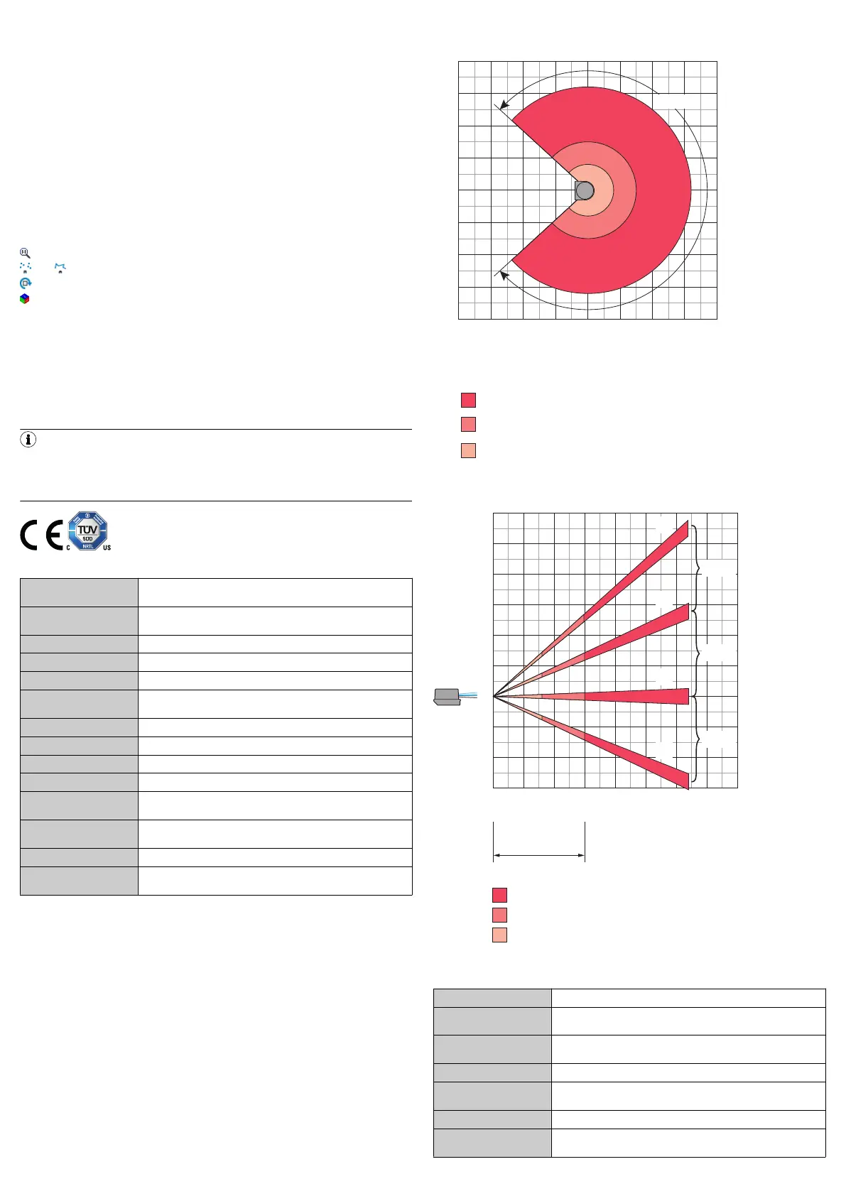
Working range diagram
Scanning range in m
Scanning range in m
–20–40 20 40 60
–60
0
Scanning range max. 64 m
Scanning range for objects up to 10 % Remission 16 m
–40
40
–80
60
–20
20
0
Scanning range for objects up to 90 % remission 30 m
80
–60
275°
80
–80
Figure 8: Working area diagram, top view
4
3
2
1
2,5°
2,5°
2,5°
Height in m (ft)
1
(
3.28
)
2
(
6.56
)
3
(
9.84
)
4
(
13.12
)
5
(
16.41
)
6
(19.69)
–1
(–
3.28
)
–2
(–
6.56
)
–3
(–
9.84
)
0
0
Radius in m (ft)
20
(65.62)
40
(131.24)
60
(
196.86
)
80
(
262.48
)
Max. scanning range
10 % Remission
90 % Remission
1
2
3
4
Layer 4
Layer 3
Layer 2
Layer 1
Typical
scanning range
Figure 9: Working area diagram, side view
8.2 Performance
Scan/frame rate 55000 … 165000 measuring points/second
Response time
1
typically 20 ms (4 layers), typically 80 ms (1 layer)
min. 7 ms, max. 84 ms + 1 scan
Systematic error ± 60 mm
Temperature drift: typically ± 0.5 mm/K
Statistical error ≤ 30 mm
Integrated application Integrated field evaluation with flexible fields on 4 levels, data
output
Number of field sets Up to 64 fields
Simultaneous analysis
cases
Up to 16 analyses
8020471/12FY/2019-04-02/en MRS1000 | SICK 4

 Loading...


