For safe series connection
Figure 28: Device connection (male connector, M12, 8-pin, A-coded)
Table 9: Device connection pin assignment (male connector, M12, 8-pin, A-coded)
Pin Wire color
1)
Designation Description
1 White Out AUX LOCK Locking device application diag‐
nostic output (not safe)
2 Brown 24 V DC Voltage supply 24 V DC
3 Green RST Hardware reset connection
4 Yellow In 2 Enable input for OSSD 2
2)
5 Gray OSSD 1 Output OSSD 1
6 Pink OSSD 2 Output OSSD 2
7 Blue 0 V Voltage supply 0 V DC
8 Red In 1 Enable input for OSSD 1
2)
1)
Applies to the extension cables recommended as accessories.
2)
When used as an individual safety locking device or as the first safety locking device in a safe series con‐
nection, apply 24 V DC.
Figure 29: Device connection (male connector, M12, 5-pin, A-coded)
Table 10: Device connection pin assignment (male connector, M12, 5-pin, A-coded)
Pin Wire color
1)
Designation Description
1 Brown MAG 0 V DC Input for locking device 0 V DC
2 White Out AUX DOOR Door application diagnostic out‐
put (not safe)
3 Blue Out AUX DIA Fault application diagnostic out‐
put (not safe)
4 Black MAG +24 V DC Input for locking device 24 V DC
5 Gray N.C. Not assigned
1)
Applies to the extension cables recommended as accessories.
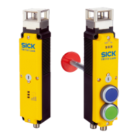
Variant with two pushbuttons
Figure 30: Device connection (male connector, M12, 8-pin, A-coded)
ELECTRICAL INSTALLATION 6
8023119/15LY/2019-10-28 | SICK O P E R A T I N G I N S T R U C T I O N S | TR110 Lock
31
Subject to change without notice