5 Mounting
5.1 Mounting instructions
•
Observe the technical data.
•
To prevent condensation, avoid exposing the device to rapid changes in tempera‐
ture.
•
The mounting site has to be designed for the weight of the device.
•
It should be mounted so that it is exposed to as little shock and vibration as possi‐
ble. Optional mounting accessories are available, see "Accessories", page 47.
•
Use a stable bracket with sufficient load-bearing capacity and suitable dimensions
for the device.
•
Ensure that the device has a clear view of the object to be detected.
•
Protect the device from moisture, contamination, and damage.
•
Ensure a sufficient level of cooling using ambient air/convection and/or heat
dissipation through mechanical mounting. Observe the permitted operating tem‐
perature, see "Technical data", page 44.
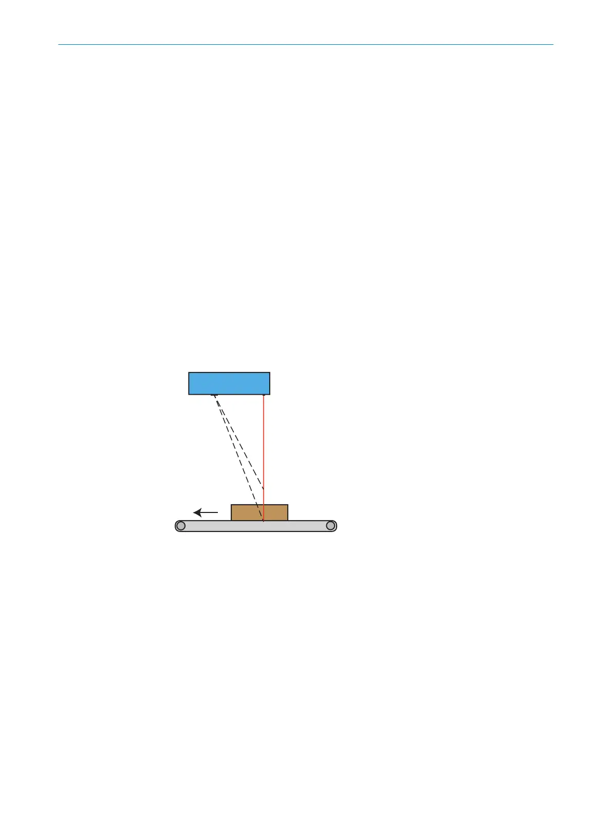
5.2 Mounting the device
Mount the device in a position above the surface to be scanned. See "Field of view
diagrams", page 22 for field of view diagrams and mounting distances. The default
scan direction is shown in figure 5. If a scan is performed in the opposite direction, the
acquired image will be mirrored.
Figure 5: Mounting position
5.3 Field of view diagrams
The maximum guaranteed image acquisition area in mm (inch) is shown for each
device variant. The brighter areas represent typical image acquisition areas.
5 MOUNTING
22
O P E R A T I N G I N S T R U C T I O N S | TriSpectorP1000 8022395/19OK/2020-12 | SICK
Subject to change without notice