■
The encoder must be an incremental encoder.
■
The encoder must have a RS-422/TTL interface. In the case of strong magnetic
fields in proximity to the TriSpectorP1000, use a recommended encoder (no.
1068997) to ensure optimal performance.
■
The connection requires two encoder channels (A/A¯ and B/B¯) to keep track of
movement and direction.
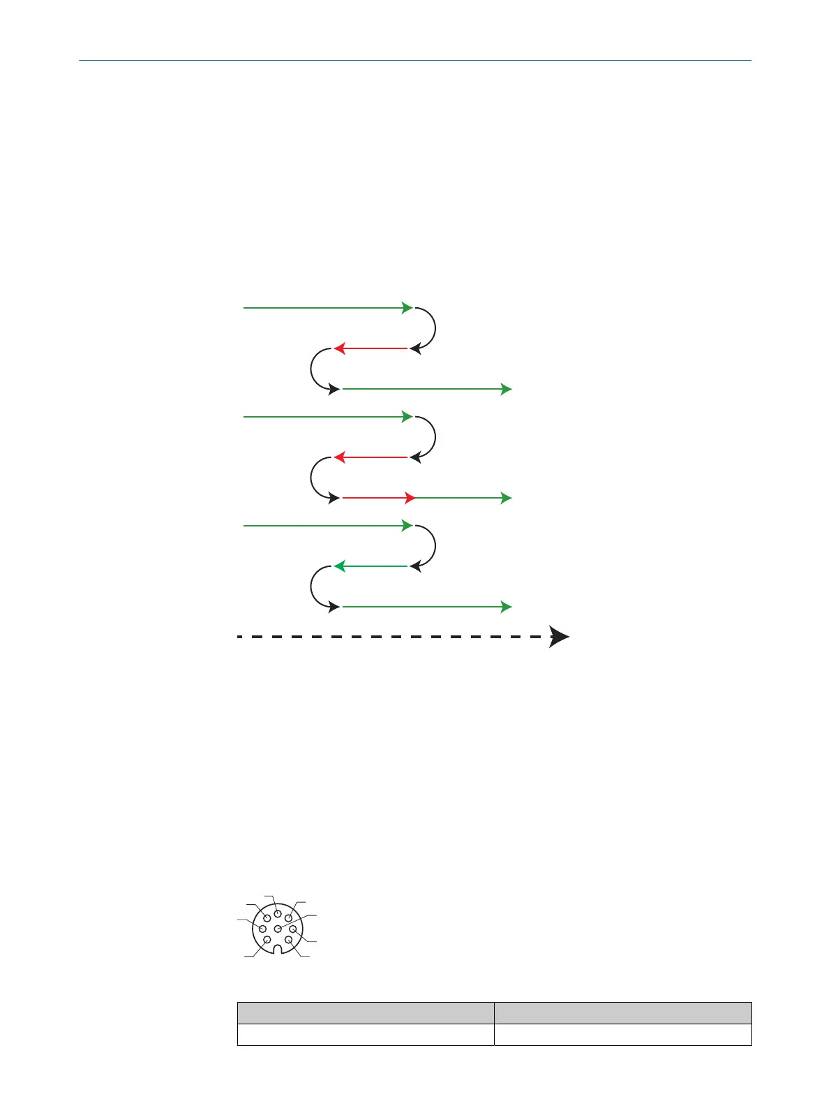
6.4.1 Encoder modes
The forward scanning direction is defined as a clockwise encoder shaft movement,
as seen from the tip of the shaft. There are five encoder pulse counter-modes: posi‐
tive/negative movement, forward/backward movement and bidirectional.
Scan 1
No scan 2
Forward scanning direction 6
Motion 5
Position Up 4
Direction Up 3
Scan 1
No scan 2
Scan 1
Figure 16: Encoder pulse counter-modes
1
Scan
2
No scan
3
Direction up
4
Position up
5
Motion
6
Forward scanning direction
6.5 Pin assignment
Encoder I/O
Figure 17: M12 female connector, 8-pin A-coded
Pin Signal
1 A/ - RS-422 inverted input
ELECTRICAL INSTALLATION 6
8022395/19OK/2020-12 | SICK O P E R A T I N G I N S T R U C T I O N S | TriSpectorP1000
31
Subject to change without notice