Pin Signal
2 A - RS-422 non-inverted input
3 B/ - RS-422 inverted input
4 B - RS-422 non-inverted input
5 (Not connected)
6 (Not connected)
7 GND (Power / Signal)
8 24 V Voltage supply output
Gigabit Ethernet
Figure 18: M12 female connector, 8-pin X-coded
Pin Signal
1 GETH_L1+
2 GETH_L1-
3 GETH_L2+
4 GETH_L3+
5 GETH_L3-
6 GETH_L2-
7 GETH_L4+
8 GETH_L4-
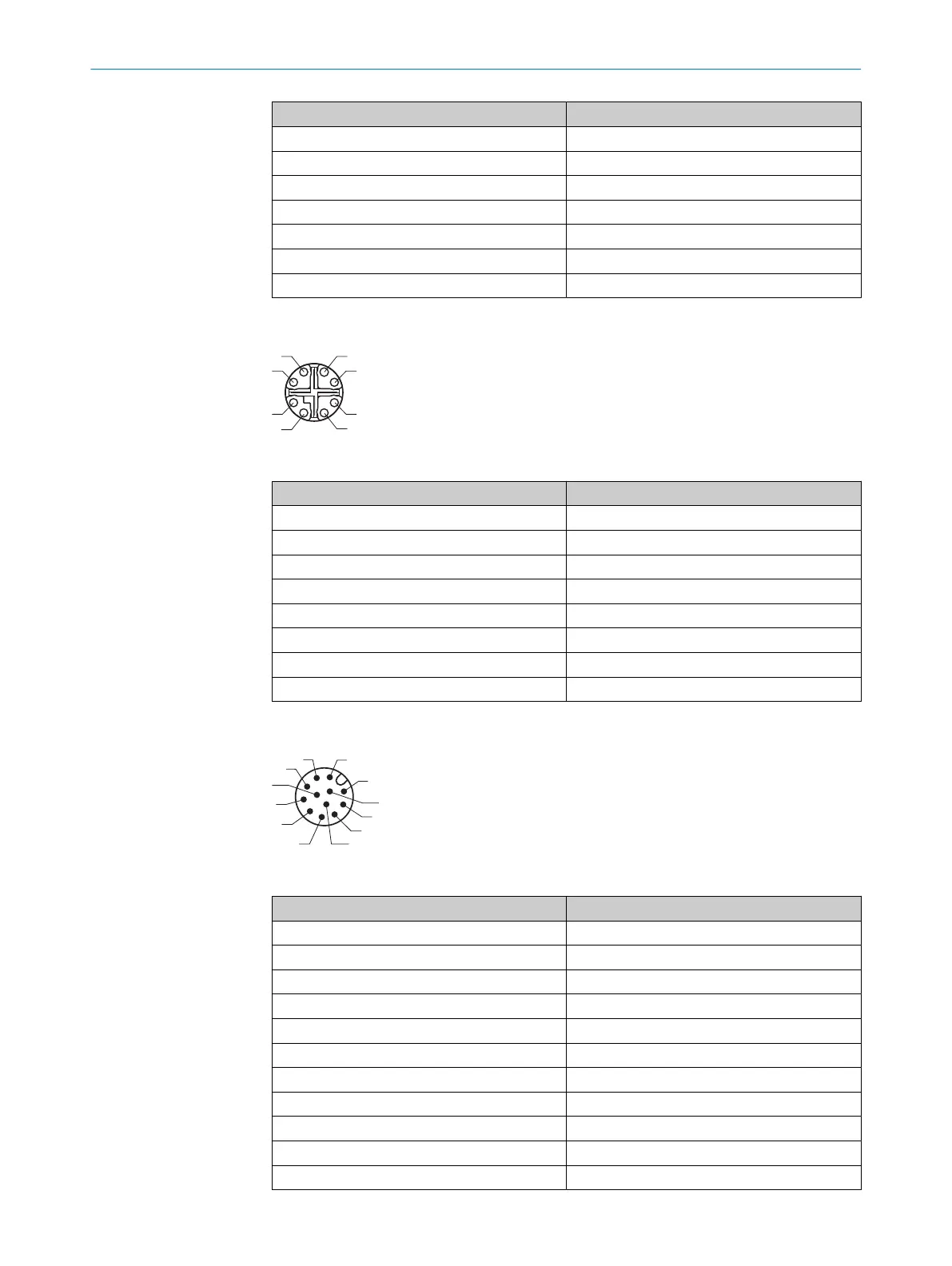
Power I/O
Figure 19: M12 male connector, 12-pin A-coded
Pin Signal
1 24 V Voltage supply input
2 Ground (Power / Signal)
3 24 V - I/O 3, Trigger in
4 24 V - I/O 4, Programmable
5 24 V - I/O 2, Input
6 24 V - I/O 5, Programmable
7 24 V - I/O 6, Programmable
8 24 V - I/O 1, Input
9 24 V - I/O 7, Programmable
10 Reserved
11 RS-232 Rx
6 ELECTRICAL INSTALLATION
32
O P E R A T I N G I N S T R U C T I O N S | TriSpectorP1000 8022395/19OK/2020-12 | SICK
Subject to change without notice