9
2687
12 2020
-
SE80 & SE100 & SE120 & SE130 & SE150
MG_0003
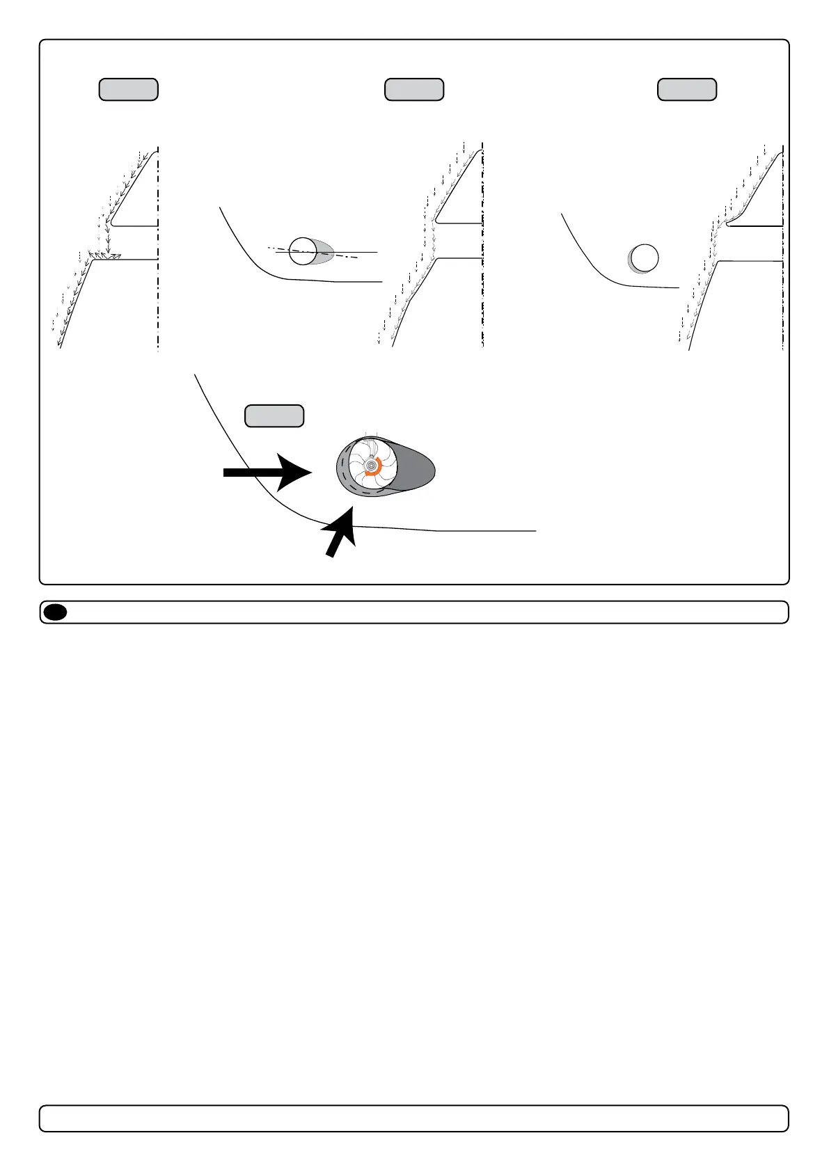
High water force
while underway
High water force
while underway
from wave contact
1 2 3
4
Water Defl ection
EN
MC_0003
1. A possible problem in sailboats or fast powerboats is that a non-rounded surface can generate drag from the back face of the tunnel, as it creates a
“ at” area facing the ow of water (1).
This problem can be solved in two diff erent ways, depending on what is possible or easier to perform.
2. The best solution which generally reduces the most drag is to make a recess in the hull at the back of the tunnel. As the back face is removed
water can ow freely past the tunnel entry. The depth and shape of this recess will depend on the boat and the angle facing up/ down aft of the
tunnel insert. Normally it is angled slightly down because of the water ow on this area (2).
3. Making a de ector/ spoiler in front and underneath the tunnel can also reduce damage to the thruster and drag. The de ector/ spoiler will push the
water ow out from the hull so water can pass by the back face of the tunnel. The shape and size of this de ector/ spoiler will depend on the hull
shape. The easiest way of making the de ector/ spoiler is to retain a part of the lower forward area of the tunnel while installing the tube. Use this
area as support to mould a soft curve/spoiler shape from the hull. (3).
4. The thruster propeller can spin (passively) producing noise while sailing or cruising as water is forced through the tunnel. Water ow directed
through the tunnel at high speeds, during turning or as the boat bumps waves while underway can also damage the thruster (4).
(NB: As a rule, you should not see the back face of the tunnel when standing directly in front of the boat looking aft.)
MG_0004
Min
Pos. B
Pos. A
1
1
2
3
4 65
MG_0048
Increase tunnel length to protect
the propeller from water forces
when high-speed cruising.
Water
Forces
Increase tunnel length to prevent
a circular water vacuum cavity
between the propeller and the
hull of the boat.
STANDARD USE FLAT BOTTOM HULL HIGH-SPEED OPERATION
Do not allow the variable length of the tunnel walls to vary in length
excessively.
EG. the top tunnel wall is x 4 longer than the bottom wall.
Cavitation
Water flow must have
space to "straighten"
itself for best
performance.
The gear leg/ propeller(s) must
never extend out of the tunnel
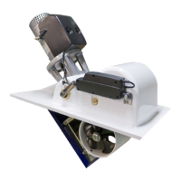
Tunnel installation in sailboats
EN
Some sailboats have a at bottom and shallow draft in the bow section. This can make installing the thruster as far forward from the boats main pivot
point diffi cult. (Fig. 1).
However, it is possible to install a tunnel thruster in most sailboats, even when the hull does not directly support the tting of a tunnel.
Instead t the tunnel halfway into the underneath section of the existing hull. Strengthen it with a de ector/ spoiler directing the water ow around the
tunnel. This will allow installation of the thruster in the proper position on the boat, maintaining the reliability and space advantages of the tunnel thruster.
This installation is being used by some of the world’s largest sailboat builders and has proven to give little to no speed loss during normal cruising. This
can also be an installation method for at bottomed barges to avoid extremely long tunnels and large oval tunnel openings in the hull.
MC_0003

 Loading...