17
2687
12 2020
-
SE80 & SE100 & SE120 & SE130 & SE150
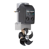
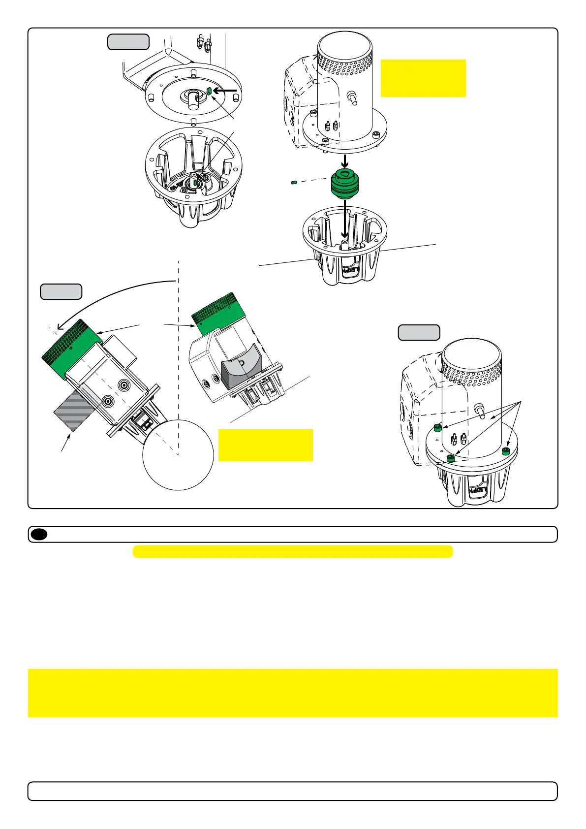
Motor Installation
EN
1. Install the motor onto the motor bracket ensuring the couplings are engaged together correctly (top and bottom). (NB: The motor can be placed
in all directions on the motor bracket. However, ensure the cable terminals are accessible for electrical installation later.)
2. If you are installing the motor at an angle of more than 30º off vertical, the motor will require separate/ additional support. (NB: Do not position
supports on the motors top cap.)
3. Fasten the bolts holding the motor to the motor bracket with the above torque.
4. Check the drive shafts are engaged by rotating the propeller. (NB: Rotating the propellers can be hard due to the gear reduction and the
motor, however the propeller must be able to rotate via hand power.)
MC_0019
! Please refer to the graphic for special considerations relating to your model !
IMPORTANT
The thruster motor assembly must be protected using suitable covering to avoid dust/debris ingress from fabrication/maintenance/
shipbuilding operations. On completion of operations, the cover must be removed before operating the thruster.
MG_0043
1
2
3
IMPORTANT
Do not position support
on the motor cap.
FASTEN
(33 Nm)
(24 lb/ft)
Motor support
Motor
Cap
> 30°
Holding Key
IMPORTANT
Ensure the holding
key and coupling are
aligned when fitted
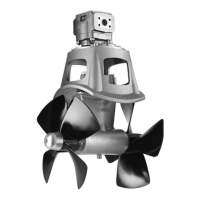
Propeller Installation
EN
MC_0018
! Please refer to the graphic for special considerations relating to your model !
1. Centre the drive pin and Insert the propeller onto the shaft spine. Rotate the propeller until the drive pin aligns with the internal slot in the propeller.
2. Insert the washer to the end of the shaft spline. Tighten with the propeller lock-nut.
3. Insert the anode to the end of the propeller and tighten the anode holding screw. Apply a thread glue (Loctite 243 or similar) to ensure that the
anode holding screw does not un-screw itself from during the rotation of the propeller.
4. Apply antifouling to the gear leg and propeller. Do not apply antifouling to any rubber elements of the gear leg or anodes.
MG_0033
DRIVE PIN
PROPELLER
WASHER
LOCK NUT
ANODE
ANODE HOLDING
SCREW
Apply Loctite 243 or similar
Anitfouling
 Loading...