19
2687
12 2020
-
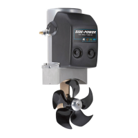
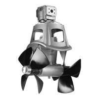
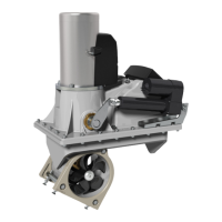
SE80 & SE100 & SE120 & SE130 & SE150
Electrical Specifi cations
EN
MC_0044
*Valid for DC motors
Model Size
System
Voltage
Nominal
current
draw
Min. battery
CCA
Rec. fuse
<7m total + & - 7-14m total + & - 15-21m total + & - 22-28m total + & - 28-35m total + & - 36-45m total + & -
Min. Rec. Min. Rec. Min. Rec. Min. Rec. Min. Rec. Min. Rec.
*20/110S 12 V 150 A
DIN: 200
SAE: 380
EN: 330
ANL 150
mm2 25 35 35 50 50 70 70 95 95 95 120 2 x 70
AWG 3 2 2 1/0 1/0 2/0 2/0 3/0 3/0 3/0 2 x 4/0 2 x 2/0
*25/110S 12 V 200 A
DIN: 200
SAE: 380
EN: 330
ANL 150
mm2 25 35 50 50 70 70 95 95 120 120 2 x 70 2 x 70
AWG 3 2 1/0 1/0 2/0 2/0 3/0 3/0 4/0 4/0 2 x 2/0 2 x 2/0
*30/125S 12 V 245 A
DIN: 200
SAE: 380
EN: 330
ANL 150
mm2 35 50 50 70 70 95 95 120 120 2 x 70 2 x 70 2 x 95
AWG 2 1/0 1/0 2/0 2/0 3/0 3/0 4/0 4/0 2 x 2/0 2 x 2/0 2 x 3/0
*40/125S 12 V 315 A
DIN: 300
SAE: 570
EN: 520
ANL 250
mm2 35 50 70 95 95 120 120 2 x 70 2 x 95 2 x 95 2 x 120 2x 120
AWG 2 1/0 2/0 3/0 3/0 4/0 4/0 2 x 2/0 2 x 3/0 2 x 3/0 2 x 4/0 2 x 4/0
*50/140S
12 V 370 A
DIN: 350
SAE: 665
EN: 600
ANL 325
mm2 50 50 70 95 120 2 x 70 2 x 70 2 x 95 2 x 95 2 x 120 2 x 120 2 x 120
AWG 1/0 1/0 2/0 3/0 4/0 2 x 2/0 2 x 2/0 2 x 3/0 2 x 3/0 2 x 4/0 2 x 4/0 2 x 4/0
24 V 170 A
DIN: 175
SAE :332
EN: 280
ANL 150
mm2 25 25 25 35 35 50 35 50 50 70 70 70
AWG 3 3 3 2 2 1/0 2 1/0 1/0 2/0 2/0 2/0
*60/185S
12 V 370 A
DIN: 350
SAE: 665
EN: 600
ANL 325
mm2 50 50 70 95 120 2 x 70 2 x 70 2 x 95 2 x 95 2 x 120 2 x 120 2 x 120
AWG 1/0 1/0 2/0 3/0 4/0 2 x 2/0 2 x 2/0 2 x 3/0 2 x 3/0 2 x 4/0 2 x 4/0 2 x 4/0
24 V 170 A
DIN: 175
SAE: 332
EN: 280
ANL 150
mm2 25 25 25 35 35 50 35 50 50 70 70 70
AWG 3 3 3 2 2 1/0 2 1/0 1/0 2/0 2/0 2/0
*80/185T
12 V 530 A
DIN: 550
SAE: 1045
EN: 940
ANL 400
mm2 70 70 120 2 x 70 2 x 95 2 x 95 2 x 120 2x 120 2 x 120
NA NA NA
AWG 2/0 2/0 4/0 2 x 2/0 2 x 3/0 2 x 3/0 2 x 4/0 2 x 4/0 2 x 4/0
24 V 280 A
DIN: 300
SAE:570
EN: 520
ANL 250
mm2 35 35 35 50 50 70 70 95 95 120 120 2 x 95
AWG 2 2 2 1/0 1/0 2/0 2/0 3/0 3/0 4/0 4/0 2 x 3/0
*100/185T
12 V 740 A
DIN: 750
SAE: 1425
EN: 1320
ANL 500
mm2 95 95 2 x 70 2 x 95 2 x 120
NA NA NA NA NA NA NA
AWG 3/0 3/0 2 x 2/0 2 x 3/0 2 x 4/0
24 V 340 A
DIN: 400
SAE: 760
EN: 680
ANL 325
mm2 50 50 50 70 70 95 95 120 120 2 x 95 2 x 95 2 x 120
AWG 1/0 1/0 1/0
2/0 2/0 3/0 3/0 4/0 4/0 2 x 3/0 2 x 3/0 2 x 4/0
*120/215T 24V 420 A
DIN: 450
SAE: 855
EN: 760
ANL 325
mm2 70 70 70 70 70 95 95 120 120 2 x 70 2 x 70 2 x 95
AWG 2/0 2/0 2/0 2/0 2/0 3/0 3/0 4/0 4/0 2 x 2/0 2 x 2/0 2 x 3/0
*130/250T
12V 800 A
DIN: 750
SAE: 760
EN: 680
ANL 500
mm2 95 95 2 x 95 2 x 95 2 x 120 2 x 120
NA NA NA NA NA NA
AWG 3/0 3/0 2 x 2/0 2 x 3/0 2 x 4/0 2 x 4/0
24V 350 A
DIN: 400
SAE: 760
EN: 680
ANL 325
mm2 50 50 50 70 70 95 95 120 120 2 x 70 2 x 95 2 x 95
AWG 2 1/0 1/0 2/0 2/0 3/0 3/0 4/0 4/0 2 x 2/0 2 x 3/0 2 x 3/0
*150/215T 24V 610 A
DIN: 560
SAE: 1064
EN: 940
ANL 500
mm2 70 70 95 95 120 120 2 x 70 2 x 95 2 x 95 2 x 120 2 x 120 2 x 120
2 2/0 2/0 3/0 3/0 4/0 4/0 2 x 2/0 2 x 3/0 2 x 3/0 2 x 4/0 2 x 4/0 2 x 4/0
*170/250 24V 550 A
DIN: 560
SAE: 1064
EN: 940
ANL 400
mm2 70 70 70 95 95 120 120 2 x 95 2 x 95 2 x 95 2 x 120 2 x 120
AWG 2/0 2/0 2/0 3/0 3/0 4/0 4/0 2 x 3/0 2 x 3/0 2 x 3/0 2 x 4/0 2 x 4/0
*210/250 24V 500 A
DIN: 560
SAE: 1330
EN: 940
ANL 400-
500
mm2 70 70 70 95 95 120 120 2 x 70 2 x 70 2 x 95 2 x 95 2 x 120
AWG 2/0 2/0 2/0 3/0 3/0 4/0 4/0 2 x 2/0 2 x 2/0 2 x 3/0 2 x 3/0 2 x 4/0
*250/300 24V 610-670 A
DIN: 700
SAE: 1330
EN: 1170
ANL 500
mm2 70 70 95 120 120 2 x 95 2 x 95 2 x 95 2 x 95 2 x 120 2 x 120 2 x 120
AWG 2/0 2/0 3/0 4/0 4/0 2 x 3/0 2 x 3/0 2 x 3/0 2 x 3/0 2 x 4/0 2 x 4/0 2 x 4/0
*300/300
24*2
400-450A
(48V)
DIN: 400
SAE: 760
EN: 680
ANL 325
mm2 50 70 50 70 70 95 95 120 120 120 140
NA
48V AWG 1/0 2/0 1/0 2/0 2/0 3/0 3/0 4/0 4/0 4/0 4/0
MG_0019
Thruster
Motor
Battery
12V or
24V
Fuse
Main
switch
Hold in place
for securing
the end nut.
(M8) Nut
Tighten to *max
13 Nm (9.59 lb/ft)
(M10) Nut
Tighten to *max
23 Nm (16.96 lb/ft)
Multi-lug configuration
Ensure lug faces are
back to back.
Spring
washer
Spring
washer
NutNut
Lugs
Lugs
++
--
IMPORTANT
Do NOT use washers between lugs, this
causes overheating and fire. Spring
washers must be placed in the outer
position before tightening the nut.
MC_0143
Thruster Electrical Installation
EN
WARNING
Check the following with the main switch is set to off :
After all electrical connections have been completed check with an ohm meter that there is no electrical connection between
1. electro-motor fl ange and the positive terminal on the motor
2. electro-motor fl ange and the battery negative terminal on the motor
If unsure contact skilled personnel.
1. Information of electrical table.
see next page
- All power cable lengths represent the total length of the combined (+) and (-) cables.
- Battery capacity is stated as minimum cold crank capacity, (CCA).
- Use slow blow rated fuses to hold stated Amp-Draw for min. 5 minutes.
- Consider the AMP hours (Ah) for your speci c duty cycle.
2. Use appropriate sized cables and batteries with high cranking capacity to feed the thruster. The actual voltage at the motor while running the
thruster decides the motors output RPM and thrust. Use larger cables and stronger batteries for better results.
- See electrical speci cations for advised minimum cables and batteries (CCA).
3. Install the main switch as close to the battery as possible and ensure the main positive lead can take loads without noticeable voltage drop.
- Ensure the main switch (battery isolator) can be turned off independently and manually when not on board or in emergencies.
- Ensure it is easily accessible and update instructions that this should be turned off like the boat’s other main switches.
It is advised to install a fuse in the positive lead for protection against short-circuiting.
- Ensure a slow type and appropriately sized to take the amperage draw for at least 5 minutes.
(NB: For Ignition Protected installations remember to use ignition protected fuses and switches if fi tted in areas that require this feature.
Ensure to follow your national regulations)
5. Cable lugs must have adequate electrical and mechanical isolation and tted with cable lug covers.
6. Fasten cables to the required torque.
! Please refer to the graphic for special considerations relating to your model !
 Loading...