23
2687
12 2020
-
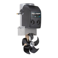
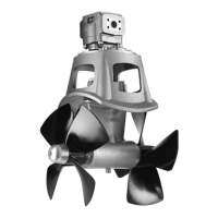
SE80 & SE100 & SE120 & SE130 & SE150
MG_0026
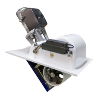
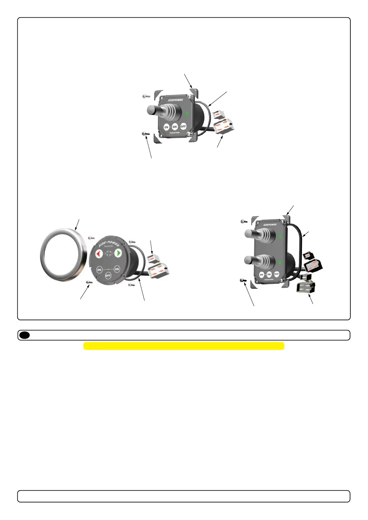
(4) COVERING CAPS
Example of control
panels
(4) COVERING CAPS
COVERING CAP
GASKET
CABLES
CABLES
CABLES
GASKET
GASKET
(4) SCREWS
(4) SCREWS
(4) SCREWS
Control Panel Installation
EN
Find a suitable location for the control panel where it does not obstruct or is obstructed by other devices. Install the control panel on a at surface where
it is easy to use.
1. Use the supplied cut-out template to mark the area to remove on your control dash.
2. Cut out the area per template for the control panel. (NB: If the front surface around your cut out is jagged or chipped, use a sealant
to assist the gasket.)
3. Place the gasket to the back face of the panel
4. Plug cables into the connectors at the rear of the control panel.
5. Insert the control panel in place and fasten screws.
6. Insert the control panels covering caps.
MC_0042
! Please refer to the graphic for special considerations relating to your model !
MG_0036
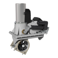
M
Thermal
switch
Electronic
interface box
6 1232i
A2
A1
4 pin
AMP
connector
On
Motor
4
2
1
3
Fuse
Battery
main
switch
1
5
4
2
6
8
9
red (+)
grey
(sig +)
blue
(sig +)
black (-)
red
grey
(sig -)
blue
(sig -)
brown
3red
Fused
inside
1A
black
7
white
NB! Make sure to not use
any electronic interface
box (delay box) older than
the 6 1232i (ex. 6 122x)
on SP75Ti, SP95Ti, and
SP125Ti.
NB! Make sure to not use
any electronic interface
box (delay box) older than
the 6 1232i (ex. 6 122x)
 Loading...