SH100/185T- SH160/215T - SP 220 HYD - SP 300 HYD - SP 550 HYD 2.5 - 2008
Wir empfehlen, die Glasberarbeiten von einem Fachmann
aus-führen zu lassen. Dieses Handbuch beinhaltet nicht alle
notwen-digen Details für diese Arbeit. Der Installateur trägt
die volle Verantwortung für eine sachgemäße Installation des
Tunnels.
Zunächst ist die Position des Tunnels aufgrund der vorange-
gange-nen Informationen und der Maße des einzubauenden
Thrusters zu bestimmen.
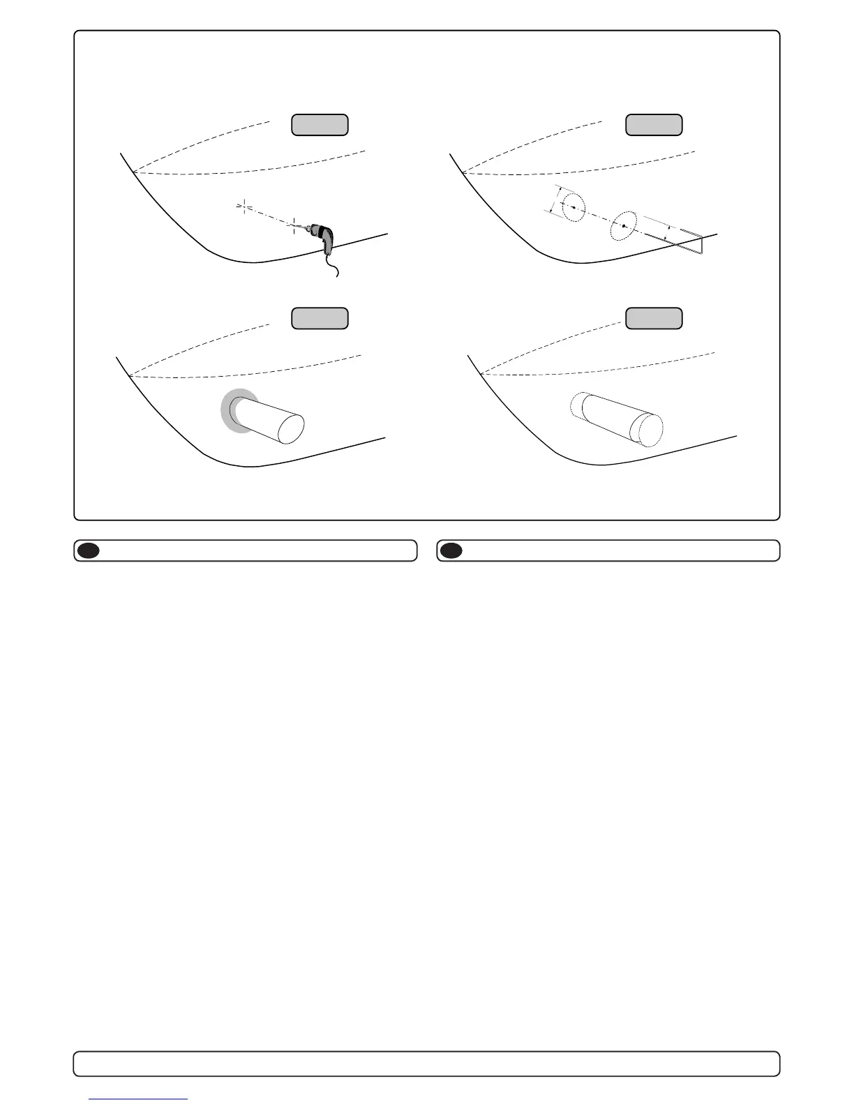
Das Zentrum auf beiden Seiten des Tunnels anreißen. Dort jew-
eils ein horizontales Loch (ø 6mm) bohren (Fig. 1).
Durch beide Löcher eine Stahlstange (ø 5mm) führen und die
Tunnelöffnung anzeichnen (Außendurchmesser des Tunnels).
Diese Fläche mit einer Stichsäge ausschneiden (Fig. 2).
Den Rumpf auf der Innenseite 12cm um das Tunnelloch frei von
Gelcoat und Polyester machen, bis Fiberglas sichtbar wird (Fig. 3).
Den Tunnel einsetzen und die Schnittlinie mit dem Rumpf an-
zeich-nen (Fig. 4). Wird ein Abweiser / Spoiler benötigt, lassen
Sie den Tunnel etwas aus dem Rumpf stehen (Vorder- und Unter-
seite des Tunnels), um einen Grundträger zu erhalten (siehe Seite
18, Fig. 2). Die Tunnelenden auf die gewünschte Form abschnei-
den und die Enden leicht anschleifen. Danach mit Aceton o.ä.
dort reinigen, wo Fiberglas aufgetragen werden soll.
NB ! Nicht im Bereich des Thrusters laminieren.
Den Tunnel im Rumpnneren einlaminieren. Dazu mind. 8 Schich-
ten zu je 300 g Glasber und Ployesterharz verwenden; vorzugs-
weise verschiedene Matten und Gewebearten (siehe Seite 18,
Fig. 1). Sollen die Tunnelenden später den optimalen 10% Radius
aufweisen, müssen gelegentlich zusätzliche Schichten aufgetra-
gen werden um eine ausreichende Rumpfstärke zu erhalten.
NB ! Jede Öffnung zwischen Tunnel und Rumpf muß vollständig
mit Poyesterharz/Glasber ausgefüllt sein. An schlecht zugäng-
lichen Stellen, wo normale Schichten nicht möglich sind, muß zu-
mindest eine Polyesterharz / Glasber Mischung eingefüllt werden.
Tunnelinstallation
D
We recomend that a professional does the breglass tting
of the tunnel. These instructions are only general, and do not
explain in any way the details of breglass work. Problems
caused by faulty installation of the tunnel, are the installers
full responsibility.
Find the position in the boat considering the information given
earlier in this manual and the applicable measurements for the
thruster model you are installing.
Mark the centre of the tunnel on both sides. Drill a 6mm hole
horizontally in these marks (Fig. 1) .
Bend a ø 5mm steel bar as shown with the "tip" bent back at the
tunnel radius and mark the circle for the tunnel opening (outside
diameter of the tunnel). Cut the hole with a jigsaw (Fig. 2).
Grind off the gelcoat and polyester so that you are down in the
“real breglass” in an area of 12cm around the hole both inside
and outside in the hull to cast the tunnel to the hull (Fig. 3).
Insert the tunnel and mark its shape to t the hull (Fig. 4). If you
are installing with a deector/spoiler, leave a part or the tunnel of
the front- and underside of the tunnel to have a base for this (see
page 12, Fig. 2). Cut the tunnel ends to the desired shape and
lightly sand its surface and clean with aceton or similar where you
are going to apply breglass.
NB! Do not cast/glass on the area were the thruster will be
placed.
Then cast the tunnel to the inside of the hull, use at least 8 layers
of 300 g glass and resin, preferrably alternating mat and rowing
types of breglass (see page 18, Fig. 1). If you are rounding the
tunnel ends to the perfect 10% radius you may in some cases
have to make further layers inside to preserve the desired hull
thickness.
NB ! Make sure that any gap between the tunell and the hull are
completely lled with resin/breglass. In areas where you can not
Tunnel installation
GB
11
Wir empfehlen, die Glasfiberarbeiten von einem Fachmann aus-
führen zu lassen. Dieses Handbuch beinhaltet nicht alle
notwen-digen Details für diese Arbeit. Der Installateur trägt die
volle Verantwortung für eine sachgemäße Installation des
Tunnels.
Zunächst ist die Position des Tunnels aufgrund der vorangegange-
nen Informationen und der Maße des einzubauenden Thrusters zu
bestimmen.
Das Zentrum auf beiden Seiten des Tunnels anreißen. Dort jeweils
ein horizontales Loch (ø 6mm) bohren (Fig. 1).
Durch beide Löcher eine Stahlstange (ø 5mm) führen und die
Tunnelöffnung anzeichnen (Außendurchmesser des Tunnels).
Diese Fläche mit einer Stichsäge ausschneiden (Fig. 2).
Den Rumpf auf der Innenseite 12cm um das Tunnelloch frei von
Gelcoat und Polyester machen, bis Fiberglas sichtbar wird (Fig. 3).
Den Tunnel einsetzen und die Schnittlinie mit dem Rumpf anzeich-
nen (Fig. 4). Wird ein Abweiser / Spoiler benötigt, lassen Sie den
Tunnel etwas aus dem Rumpf stehen (Vorder- und Unterseite des
Tunnels), um einen Grundträger zu erhalten (siehe Seite 18, Fig. 2).
Die Tunnelenden auf die gewünschte Form abschneiden und die
Enden leicht anschleifen. Danach mit Aceton o.ä. dort reinigen, wo
Fiberglas aufgetragen werden soll.
NB ! Nicht im Bereich des Thrusters laminieren.
Den Tunnel im Rumpfinneren einlaminieren. Dazu mind. 8 Schich-
ten zu je 300 g Glasfiber und Ployesterharz verwenden; vorzugs-
weise verschiedene Matten und Gewebearten (siehe Seite 18, Fig.
1). Sollen die Tunnelenden später den optimalen 10% Radius
aufweisen, müssen gelegentlich zusätzliche Schichten aufgetra-
gen werden um eine ausreichende Rumpfstärke zu erhalten.
NB ! Jede Öffnung zwischen Tunnel und Rumpf muß vollständig
mit Poyesterharz/Glasfiber ausgefüllt sein. An schlecht zugäng-
lichen Stellen, wo normale Schichten nicht möglich sind, muß zu-
mindest eine Polyesterharz / Glasfiber Mischung eingefüllt werden.
Tunnelinstallation
D
We recomend that a professional does the fibreglass fitting of
the tunnel. These instructions are only general, and do not
explain in any way the details of fibreglass work. Problems
caused by faulty installation of the tunnel, are the installers full
responsibility.
Find the position in the boat considering the information given
earlier in this manual and the applicable measurements for the
thruster model you are installing.
Mark the centre of the tunnel on both sides. Drill a 6mm hole
horizontally in these marks (Fig. 1) .
Bend a ø 5mm steel bar as shown with the "tip" bent back at the
tunnel radius and mark the circle for the tunnel opening (outside
diameter of the tunnel). Cut the hole with a jigsaw (Fig. 2).
Grind off the gelcoat and polyester so that you are down in the
“real fibreglass” in an area of 12cm around the hole both inside and
outside in the hull to cast the tunnel to the hull (Fig. 3).
Insert the tunnel and mark its shape to fit the hull (Fig. 4). If you are
installing with a deflector/spoiler, leave a part or the tunnel of the
front- and underside of the tunnel to have a base for this (see page
12, Fig. 2). Cut the tunnel ends to the desired shape and lightly
sand its surface and clean with aceton or similar where you are
going to apply fibreglass.
NB! Do not cast/glass on the area were the thruster will be placed.
Then cast the tunnel to the inside of the hull, use at least 8 layers of
300 g glass and resin, preferrably alternating mat and rowing types
of fibreglass (see page 18, Fig. 1). If you are rounding the tunnel
ends to the perfect 10% radius you may in some cases have to
make further layers inside to preserve the desired hull thickness.
NB ! Make sure that any gap between the tunell and the hull are
completely filled with resin/fibreglass. In areas where you can not
access to make normal layers of resin/fibreglass, a resin/ fibreglass
mixture must be filled in that area.
R
D
Tunnel installation
Fig. 1
Fig. 3 Fig. 4
Fig. 2
GB
SH100/185T - SP 220 HYD - SP 300 HYD - SP 550 HYD
2.4 - 2007
11
 Loading...