SH100/185T- SH160/215T - SP 220 HYD - SP 300 HYD - SP 550 HYD 2.5 - 2008
6
Tunnelplazierung soweit vorne wie möglich (Fig. 1)
Um einen möglichst großen Abstand vom Drehpunkt des Schiffes zu
erreichen, ist der Sidepower möglichst weit vorne einzubauen.
Eine Vergrößerung des Abstandes vom Drehpunkt des Schiffes
hat eine direkte Auswirkung auf die verfügbare Schubkraft.
Beispiel :
A: 100kg Schubkraft x 11m = 1100kgm zum Wenden des Bootes
B: 100kg Schubkraft x 10m = 1000kgm zum Wenden des
Bootes
In Beispiel A stehen damit 10% mehr Schubkraft zur Verfügung.
Den Tunnel so tief wie möglich positionieren (Fig. 2)
Den Tunnel aus zwei Gründen so tief wie möglich positionieren:
1. Damit nicht Luft mitangesaugt wird, die die Schubkraft voll-
ständig herabsetzt.
2. Um einen möglichst hohen Wasserdruck zu erhalten, um die
maximale Efzienz des Propellers erreichen.
Die Oberkante des Tunnels muß mind. einen halben Tunnel-du-
rchmesser unterhalb der Wasserlinie liegen. Dieser Wert ist ein
absolutes Minimum. Besser ist ein Wert von ca. 3/4 des Tun-
neldurchmessers (). Optimal ist eine Abstand von 1/1 x Tunnel-
durchmesser () zur Wasserlinie.
Liegt die Oberkante des Tunnels 30-35cm* / 1Fuß unterhalb der
Wasserlinie, können andere Faktoren berücksichtigt werden.
Optimale Tunnellänge
Bei einem zu langem Tunnel reduziert der Reibungsverlust die
Wassergeschwindigkeit und damit die Schubkraft.
Bei einem zu kurzem Tunnel (häug im unteren Bereich des Tun-
nels) können Kavitationsprobleme entstehen, da sich das Wasser
nicht gerade auszurichten kann (Fig. 3/4). Diese Kavitation ist
leistungsreduzierend und kann starken Lärm verursachen.
Die optim. Tunnellänge ist das 2-4 fache des Tunneldurchmessers.
Tunnellängen von mehr als dem 6-7 fachen des Tunneldurch-
messers sollten vermieden werden, da dadurch die Leistung
Positionierung von Tunnel / Thruster
D
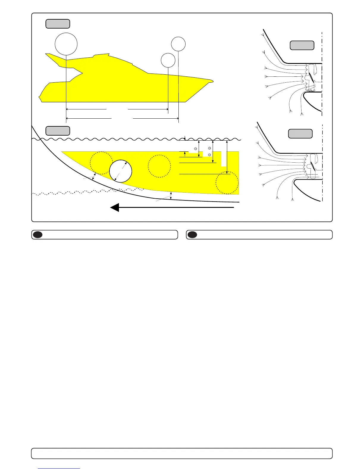
The Thruster should be as far forward as possible (Fig. 1)
Because of the leverage effect around the boats pivot point, it is
very important for the thrusters actual effect in the boat to get it
as far for-ward as possible. The relative distance change from the
boats pivot point to the thruster will be the change of actual thrust
for the boat.
Example :
A: 100kg thrust x 11m leverage = 1100kgm torque to rot. the boat
B: 100kg thrust x 10m leverage = 1000kgm torque to rot. the boat
In position A you will get 10% more thrust to turn the boat around.
The thruster should be placed as deep as possible (Fig. 2)
The tunnel should be placed as deep as possible for two reasons:
1. So that it does not suck down air from the surface which will
destroy the thrust completely.
2. To get as high as possible a water pressure to get maximum
efciency from the propeller.
Generally the top of the tunnel should be a minimum of 1/2 x the
tunnel diameter below the waterline. This is an absolute minimum
and we recommend that it is at least 3/4 x tunnel diameter ()
below the waterine. A really good distance is about 1/1 x tunnel
diameter () below the waterline.
When you get the top of the tunnel 30-35 cm* / 1 feet below the
surface, other factors should be considered more important, i.e.
moving the thruster further forward.
Optimal tunnel length
If the tunnel gets to long, the friction inside will reduce the water
speed and thereby the thrust.
If the tunnel gets to short (normally only in the bottom section of
the tunnel) you can get cavitation problems as the water will not
have had time to “straigthen” itself before reaching the propeller
(Fig. 3/4). This caviation will reduce performance as well as creat-
ing a lot of noise.
The optimal tunnel length is 2 to 4 x tunnel diameter and you
should avoid tunnels longer than 6 to 7 times the tunnel diameter
Positioning of the tunnel / thruster
GB
SH100/185T - SP 220 HYD - SP 300 HYD - SP 550 HYD
2.4 - 2007
6
Tunnelplazierung soweit vorne wie möglich (Fig. 1)
Um einen möglichst großen Abstand vom Drehpunkt des Schiffes zu
erreichen, ist der Sidepower möglichst weit vorne einzubauen.
Eine Vergrößerung des Abstandes vom Drehpunkt des Schiffes
hat eine direkte Auswirkung auf die verfügbare Schubkraft.
Beispiel :
A: 100kg Schubkraft x 11m = 1100kgm zum Wenden des Bootes
B: 100kg Schubkraft x 10m = 1000kgm zum Wenden des Bootes
In Beispiel A stehen damit 10% mehr Schubkraft zur Verfügung.
Den Tunnel so tief wie möglich positionieren (Fig. 2)
Den Tunnel aus zwei Gründen so tief wie möglich positionieren:
1. Damit nicht Luft mitangesaugt wird, die die Schubkraft
vollständig herabsetzt.
2. Um einen möglichst hohen Wasserdruck zu erhalten, um die
maximale Effizienz des Propellers erreichen.
Die Oberkante des Tunnels muß mind. einen halben Tunnel-
durchmesser unterhalb der Wasserlinie liegen. Dieser Wert ist ein
absolutes Minimum. Besser ist ein Wert von ca. 3/4 des
Tunneldurchmessers (-). Optimal ist eine Abstand von 1/1 x
Tunneldurchmesser (--) zur Wasserlinie.
Liegt die Oberkante des Tunnels 30-35cm* / 1Fuß unterhalb der
Wasserlinie, können andere Faktoren berücksichtigt werden.
Optimale Tunnellänge
Bei einem zu langem Tunnel reduziert der Reibungsverlust die
Wassergeschwindigkeit und damit die Schubkraft.
Bei einem zu kurzem Tunnel (häufig im unteren Bereich des
Tunnels) können Kavitationsprobleme entstehen, da sich das
Wasser nicht gerade auszurichten kann (Fig. 3/4). Diese Kavitation
ist leistungsreduzierend und kann starken Lärm verursachen.
Die optim. Tunnellänge ist das 2-4 fache des Tunneldurchmessers.
Tunnellängen von mehr als dem 6-7 fachen des Tunneldurch-
messers sollten vermieden werden, da dadurch die Leistung
reduziert wird.
Positionierung von Tunnel / Thruster
D
The Thruster should be as far forward as possible (Fig. 1)
Because of the leverage effect around the boats pivot point, it is very
important for the thrusters actual effect in the boat to get it as far for-
ward as possible. The relative distance change from the boats pivot
point to the thruster will be the change of actual thrust for the boat.
Example :
A: 100kg thrust x 11m leverage = 1100kgm torque to rot. the boat
B: 100kg thrust x 10m leverage = 1000kgm torque to rot. the boat
In position A you will get 10% more thrust to turn the boat around.
The thruster should be placed as deep as possible (Fig. 2)
The tunnel should be placed as deep as possible for two reasons:
1. So that it does not suck down air from the surface which will
destroy the thrust completely.
2. To get as high as possible a water pressure to get maximum
efficiency from the propeller.
Generally the top of the tunnel should be a minimum of 1/2 x the
tunnel diameter below the waterline. This is an absolute minimum
and we recommend that it is at least 3/4 x tunnel diameter (-)
below the waterine. A really good distance is about 1/1 x tunnel
diameter (--) below the waterline.
When you get the top of the tunnel 30-35 cm* / 1 feet below the
surface, other factors should be considered more important, i.e.
moving the thruster further forward.
Optimal tunnel length
If the tunnel gets to long, the friction inside will reduce the water
speed and thereby the thrust.
If the tunnel gets to short (normally only in the bottom section of the
tunnel) you can get cavitation problems as the water will not have
had time to “straigthen” itself before reaching the propeller (Fig. 3/4).
This caviation will reduce performance as well as creating a lot of
noise.
The optimal tunnel length is 2 to 4 x tunnel diameter and you
should avoid tunnels longer than 6 to 7 times the tunnel diameter
as the performance reduction is then clearly noticeable.
Positioning of the tunnel / thruster
GB
A = 11,0m
B = 10,0m
A
B
Pivot
point
m
i
n
.
1
/
3
Ø
Ø
m
i
n
.
1
/
3
Ø
3/4Ø
-
1/1 Ø
--
30 - 35 cm*
min.
1/2Ø
Fig. 1
Fig. 2
Fig. 3
Fig. 4
 Loading...