SH100/185T- SH160/215T - SP 220 HYD - SP 300 HYD - SP 550 HYD 2.5 - 2008
1. Für genügend Öldruck im Getriebegehäuse muß der Getriebe-
ölbehälter oberhalb der Wasserlinie montiert werden. Der
Ab-stand muß mind. 20% der Distanz von Wasserline zum
Zentrum des Tunnels betragen.
2. Den Schlauch für das Öl am Vorratsbehälter und am vorge-
sehenen Nippel der Motorhalterung befestigen. Die beiden
Schlauchklemmen anziehen. Sicherstellen, daß das Öl unge-
hindert und direkt in das Getriebegehäuse ießen kann.
3. Den Vorratsbehälter mit Getriebeöl EP90 füllen.
4. Wenn das Getriebegehäuse nicht schon vorher befüllt wurde,
die Ölablaßschraube (1) öffnen, bis Öl austritt, dann sicher
festziehen. Immer die Kupferdichtung (1) verwenden.
5. Den Klebestreifen über der Propellerxierung (2) entfernen.
Falls auf den Propellerwellen nicht mehr ausreichend wasser-
festes Fett vorhanden ist, neues bzw. mehr Fett auftragen.
Da-durch können die Propeller später ohne Probleme
abgenommen werden.
6 Die Propeller aufstecken und bis zum Anschlag schieben.
Der mit LH gekennzeichnete Propeller muß auf der Backbord
Seite stehen, der mit RH gekennzeichnete Propeller auf der
Steuer-bord Seite. Die Propeller müssen sich frei drehen
können und im Tunnel möglichst zentriert sein. Sie können
in gleicher oder in entgegengesetzte Ausrichtung montiert
werden.
7. Die Befestigungsschraube (3) anziehen.
8. Die Zinkanode (4) mit der Befestigungsschraube (5) anbrin-
gen. Locktite o.ä. verwenden, damit sich die Schraube durch
die Rotation des Propellers nicht löst.
Teile:
1 : Ölablaßschraube mit Dichtung 4 : Propellermutter
2 : Propellerxierung 5 : Zinkanode
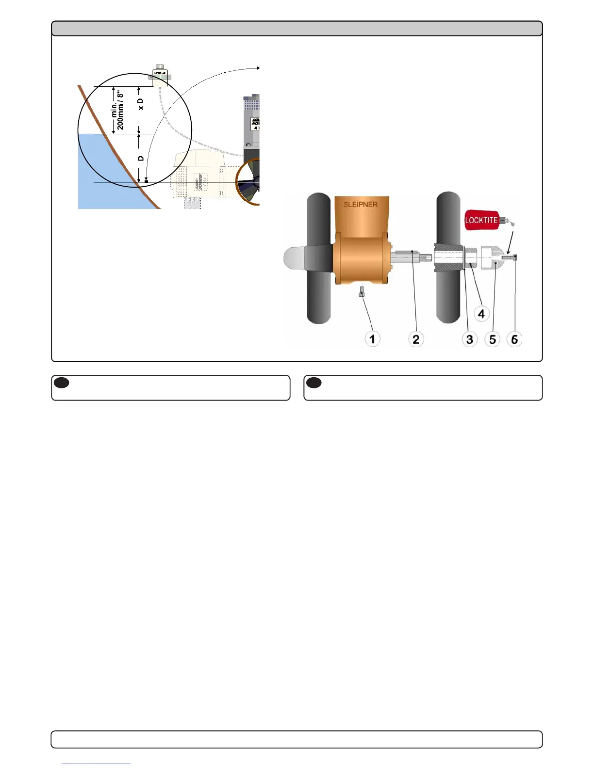
1. Fit the oil tank above the waterline by atleast 20% of the
distance from the waterline to the centre of the tunnel.
This is for ensuring enough overpressure of oil in the
gearhouse.
2. Fit the oil tube to the tank and the feed pipe in the motor
bracket. Tighten the two tube clamp screws. Make sure that
the oil-tube has no loops that makes an airlock to stop the oil
ow and has a good angle to allow the oil to ow freely into
the gearhouse.
3. Fill the oil tank with gear oil type EP90.
4. If you did not prell the gearhouse, open the oil drain screw
(1) until oil comes through, then tighten it securely and make
sure that the copper gasket (1) is present.
5. Remove the tape holding the keys (2) to the propeller shafts.
Check that the waterproof grease applied at the factory is still
on both propeller shafts. If not, apply new / more. This is to
ensure you can get of the propellers if they ate mounted for a
long time period.
6. Fit the propellers to the shafts with the LH marked propeller
on the port side and the RH marked propeller on the starboard
side. Turn them to again make sure they move freely and as
much in the centre of the tunnel as you have managed. They
can be tted either in-line or in opposite positions.
7. Tighten the lock nuts (3).
8. Place the zinkanode (4) in its designated position and tighten
the zincanodes holding screw (5). Apply a thread glue
(Locktite or similar) to ensure that the zincanodes holding
screw does not un-screw itself from the propellers rotation.
Parts description:
1 : Oil drain screw with washer 4 : Propeller lock nut
2 : Keys 5 : Zinc anode
Ölvorratsbehälter & Propeller
SP 220 HYD / SP 300 HYD / SP 550 HYD
D
Fitting oil tank & propellers
SP 220 HYD / SP 300 HYD / SP 550 HYD
GB
17
1. Für genügend Öldruck im Getriebegehäuse muß der Getriebe-
ölbehälter oberhalb der Wasserlinie montiert werden. Der Ab-
stand muß mind. 20% der Distanz von Wasserline zum Zentrum
des Tunnels betragen.
2. Den Schlauch für das Öl am Vorratsbehälter und am vorge-
sehenen Nippel der Motorhalterung befestigen. Die beiden
Schlauchklemmen anziehen. Sicherstellen, daß das Öl unge-
hindert und direkt in das Getriebegehäuse fließen kann.
3. Den Vorratsbehälter mit Getriebeöl EP90 füllen.
4. Wenn das Getriebegehäuse nicht schon vorher befüllt wurde,
die Ölablaßschraube (1) öffnen, bis Öl austritt, dann sicher
festziehen. Immer die Kupferdichtung (1) verwenden.
5. Den Klebestreifen über der Propellerfixierung (2) entfernen.
Falls auf den Propellerwellen nicht mehr ausreichend wasser-
festes Fett vorhanden ist, neues bzw. mehr Fett auftragen. Da-
durch können die Propeller später ohne Probleme
abgenommen werden.
6 Die Propeller aufstecken und bis zum Anschlag schieben. Der
mit LH gekennzeichnete Propeller muß auf der Backbord Seite
stehen, der mit RH gekennzeichnete Propeller auf der Steuer-
bord Seite. Die Propeller müssen sich frei drehen können und
im Tunnel möglichst zentriert sein. Sie können in gleicher oder in
entgegengesetzte Ausrichtung montiert werden.
7. Die Befestigungsschraube (3) anziehen.
8. Die Zinkanode (4) mit der Befestigungsschraube (5) anbrin-
gen. Locktite o.ä. verwenden, damit sich die Schraube durch
die Rotation des Propellers nicht löst.
Teile:
1 : Ölablaßschraube mit Dichtung 4 : Propellermutter
2 : Propellerfixierung 5 : Zinkanode
3 : Scheibe 6 : Schraube für Zinkanode
1. Fit the oil tank above the waterline by atleast 20% of the distance
from the waterline to the centre of the tunnel.
This is for ensuring enough overpressure of oil in the gearhouse.
2. Fit the oil tube to the tank and the feed pipe in the motor
bracket. Tighten the two tube clamp screws. Make sure that the
oil-tube has no loops that makes an airlock to stop the oil flow
and has a good angle to allow the oil to flow freely into the
gearhouse.
3. Fill the oil tank with gear oil type EP90.
4. If you did not prefill the gearhouse, open the oil drain screw (1)
until oil comes through, then tighten it securely and make sure
that the copper gasket (1) is present.
5. Remove the tape holding the keys (2) to the propeller shafts.
Check that the waterproof grease applied at the factory is still
on both propeller shafts. If not, apply new / more. This is to
ensure you can get of the propellers if they ate mounted for a
long time period.
6. Fit the propellers to the shafts with the LH marked propeller on
the port side and the RH marked propeller on the starboard
side. Turn them to again make sure they move freely and as
much in the centre of the tunnel as you have managed. They
can be fitted either in-line or in opposite positions.
7. Tighten the lock nuts (3).
8. Place the zinkanode (4) in its designated position and tighten
the zincanodes holding screw (5). Apply a thread glue (Locktite
or similar) to ensure that the zincanodes holding screw does
not un-screw itself from the propellers rotation.
Parts description:
1 : Oil drain screw with washer 4 : Propeller lock nut
2 : Keys 5 : Zinc anode
3 : Washer 6 : Screw for zincanode
SP 220 HYD / SP 300 HYD / SP 550 HYD
Ölvorratsbehälter & Propeller
SP 220 HYD / SP 300 HYD / SP 550 HYD
D
Fitting oil tank & propellers
SP 220 HYD / SP 300 HYD / SP 550 HYD
GB
SH100/185T - SP 220 HYD - SP 300 HYD - SP 550 HYD
2.4 - 2007
17
0,2
 Loading...