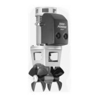
SH100/185T- SH160/215T - SP 220 HYD - SP 300 HYD - SP 550 HYD 2.5 - 2008
1. Die Mittellinie von Tunnel und Boot markieren. Damit Schub-
richtung und Kontrollpanel übereinstimmen, das Getriebege-
häuse so einbauen, daß der Verschluß des Getriebegehäuses
(der verschraubte Verschluß hinter einem der beiden Pro-
peller) Richtung Steuerbord zeigt.
2. Die Löcher mit der Dichtung (7) markieren. Maße überprüfen!
Den Thruster schiffssmittig plazieren (Fig. 1). Da der Abstand
zwischen Propellern und Tunnel wegen größtmöglicher
Performance minimal konstruiert ist, müssen für eine präzise
Installation alle Löcher auf der Tunnelmittellinie liegen.
3. Im Bereich der Motorhalterung darf kein Laminat auf dem
Tunnel sein, da dies zu einem Getriebeschaden führen
kann. Liegt die Motorhalterung nicht eben auf dem Tunnel
auf, so sind sämtliche Unebenheiten in diesem Bereich
abzuschleifen.
4. Bohren Sie das Zentrumsloch und dann die beiden
Schraubenlöcher.
5. Das Getriebegehäuse unter Verwendung der Dichtung in
den Tunnel einpassen. Den Propeller auf die Achse stecken;
dieser muß sich frei bewegen lassen und jedes Propellerblatt
muß den gleichen Abstand zum Tunnel aufweisen. Ist die
Tunnelinnenseite ungleichmäßig, etwas Sikaex o.ä. auf-
tragen, damit keine undichte Stelle auftritt.
6. Das Getriebegehäuse durch das Hauptloch im Tunnel führen
und vorsichtig mit der Motorhalterung zusammenschieben.
7. Das Getriebegehäuse und die Motorhalterung mit Hilfe der bei-
den Bolzen verschrauben (Anzugsmoment 17 Nm / 12,4 lb/ft).
1. Mark the centreline of the tunnel and the boats centreline.
The gearhouse must be tted with the gearhouse lid (the
screwed in lid behind one of the propellers) on the starbord
side of the boat for the thrust direction to correspond with the
controlpanel.
2. Use the gearhouse gasket (7) to mark the centre of the holes
and double check the measurements.
Place the thruster in the boats centreline with the bolt hole as
the centre (Fig. 1a / Fig 1b). It is absolutely necessary that all
holes are in-line with the tunnels' centreline to ensure precise
installation, as the clearance between the propellers and the
tunnel is minimal to ensure best possible performance.
3. There must be no casting where the motor bracket is to be
placed, as this will cause possible failure of the gearhouse.
The motor bracket must t steady on the tunnel, if the tunnel
is not smooth, all bumps or uneven parts must be grinded
smooth.
4. Drill the centre-hole and then the two screw-holes, SH100
dim. according to g 1a, SH160 dim. according to g. 1b
5. Try the lower-unit in the tunnel by using the gasket inside
the tunnel. Try on the propellers to make sure they are in the
middle of the tunnel and turn freely with the same clearing
from each blade to the tunnel. If the tunnel is not plain, use
some Sikaex or other sealant to ensure that no leakages
occur.
6. Push the gearhouse through the main hole in the tunnel and
push the gearhouse and motor-bracket gently together.
7. Screw the lower unit and the motor-bracket together with the
two provided bolts. Tighten with 17 Nm / 12,4 lb/ft.
Getriebe und Motorhalterung
SH 100/185 T
D
Fitting gearhouse and motor bracket
SH 100/185 T & SH160/215T
GB
13
11
SE 80/185 T - SE 100/185 T - SE 130/250T 1.0.1- 2008
Fig. 2
1. Marker båtens og tunnelens senterlinje på tunnelen.
Girhuset må plasseres med enden merket P mot babord og enden
merket S mot styrbord (Fig. 4) for at skyveretning skal korrespondere
med merkingen på kontrollpanelene.
2. Bruk girhuspakningen for å sjekke målene (7). Alle hull må være på
båtens eller tunnelens senterlinje for å får til en presis installasjon.
Dette skyldes at det er meget liten klaring mellom tunnelveggen og
propellen.
3. Tunnelen må ha en jevn overate der braketen skal festes, all støp,
evt glassber eller epoxy rester må pusses ned så braketen passer
jevnt på tunnelen. Ujevnheter her vil resultere i svikt i girhuset.
4. Bor senterhullet iht. Fig. 1a (Se80/100) eller Fig. 1b (SE130)
5. Prøv girhuset i tunnelen sammen med pakning 1m.m. Monter propell
å sjekk at den er i midten av tunnelen. Hvis propellen ikke er i midten
av tunnelen, forsøk å bruk den endre pakningen, eller begge to sam-
tidig. Hvis tunnelen ikke har en jevn overate så kan Sikaeks, eller
lignende tetningsmateriale brukes for å sikre mot lekkasje.
6. Før girhuset gjennom hovedhullet i tunnelen og monter braketten og
girhuset forsiktig sammen.
7. Skru sammen motorbraketten og girhuset med orginalbolter (Fig. 3).
Bolt tightening forces:
Bolts (2x) holding gearhouse to bracket:
SE80/100: 17 Nm (12,4 lb/ft)
SE130: 33 Nm (24lb/ft)
Montering av girhus og brakett
N
Fitting gearhouse and motor bracket
GB
Fig. 1a
PORT STARBOARD
S
P
Fig. 4
Fig. 3
1. Mark the centreline of the tunnel and the boats centreline.
The gearleg must be tted with the P-mark facing port and S-mark
facing starboard (Fig. 4) for the thrust direction to correspond with the
control panel
2. Use the gearhouse gasket (7) to mark the centre of the holes and
double check the measurements. It is absolutely
necessary that all holes are in-line with the tunnels’ centreline to
ensure precise installation, as the clearance between the
propellers and the tunnel is minimal to ensure best possible
performance.
3. There must be no casting where the motor bracket is to be placed,
as this will cause possible failure of the gearhouse. The motor
bracket must t steady on the tunnel, if the tunnel is not smooth,
all bumps or uneven parts must be grinded smooth.
4. Drill the holes according to Fig 1a (SE80/100) or Fig. 1b (SE130)
5 Try the lower-unit in the tunnel (without the zinc anodes and the
lower part of the exible coupling) by using the gasket inside the
tunnel. Try on the propellers to make sure they are in the middle of
the tunnel and turn freely with the same clearing from each blade to
the tunnel. Use sealant e.g. Sikaex to ensure that no leakages
occur.
6. Push the gearhouse through the main hole in the tunnel and push
the gearhouse and motor-bracket gently together.
7. Screw the lower unit and the motor-bracket together with the two
provided bolts (Fig. 3).
 Loading...