SH100/185T- SH160/215T - SP 220 HYD - SP 300 HYD - SP 550 HYD 2.5 - 2008
1. Die Mittellinie von Tunnel und Boot markieren. Die Propeller und
die Getriebeeinheit dürfen nicht aus dem Tunnel herausstehen.
2. Die Löcher mit der Dichtung (A) markieren. Maße überprüfen!
NB ! Da der Abstand zwischen Propeller und Tunnel minimal ist,
müssen für eine präzise Installation alle Löcher auf der Mittel-
linie des Tunnels liegen.
3. Im Bereich der Motorhalterung darf kein Laminat auf dem
Tunnel sein, da dies zu einem Getriebeschaden führen kann.
Liegt die Motorhalterung nicht eben auf dem Tunnel auf, so
sind sämtliche Unebenheiten in diesem Bereich abzuschleifen.
4. Erst das Hauptloch, dann die beiden Bolzenlöcher bohren.
5. Das Getriebegehäuse mit Getriebeöl EP90 durch die Öffnung
der Ölablaßschraube (4) befüllen. Kupferdichtung (3)
einsetzen.
6. Das Getriebegehäuse unter Verwendung der Dichtung in
den Tunnel einpassen. Den Propeller auf die Achse stecken;
dieser muß sich frei bewegen lassen und jedes Propellerblatt
muß den gleichen Abstand zum Tunnel aufweisen. Ist die
Tunnelinnenseite ungleichmäßig, etwas Sikaex o.ä. auf-
tragen, damit keine undichte Stelle auftritt.
PS ! Die Durchgänge für das Öl (2) von Dichtmasse freihalten.
7. Etwas Öl oder Fett auf die O-ringe der Motorhalterung geben,
da diese sonst beim Zusammensetzen von Getriebegehäuse
und Motorhalterung beschädigt werden können.
8. Die beiliegende Gummiplatte auf dem Tunnel plazieren.
9. Das Getriebegehäuse durch das Hauptloch im Tunnel führen
und vorsichtig mit der Motorhalterung zusammenschieben.
10. Das Getriebegehäuse und die Motorhalterung mit Hilfe der bei-
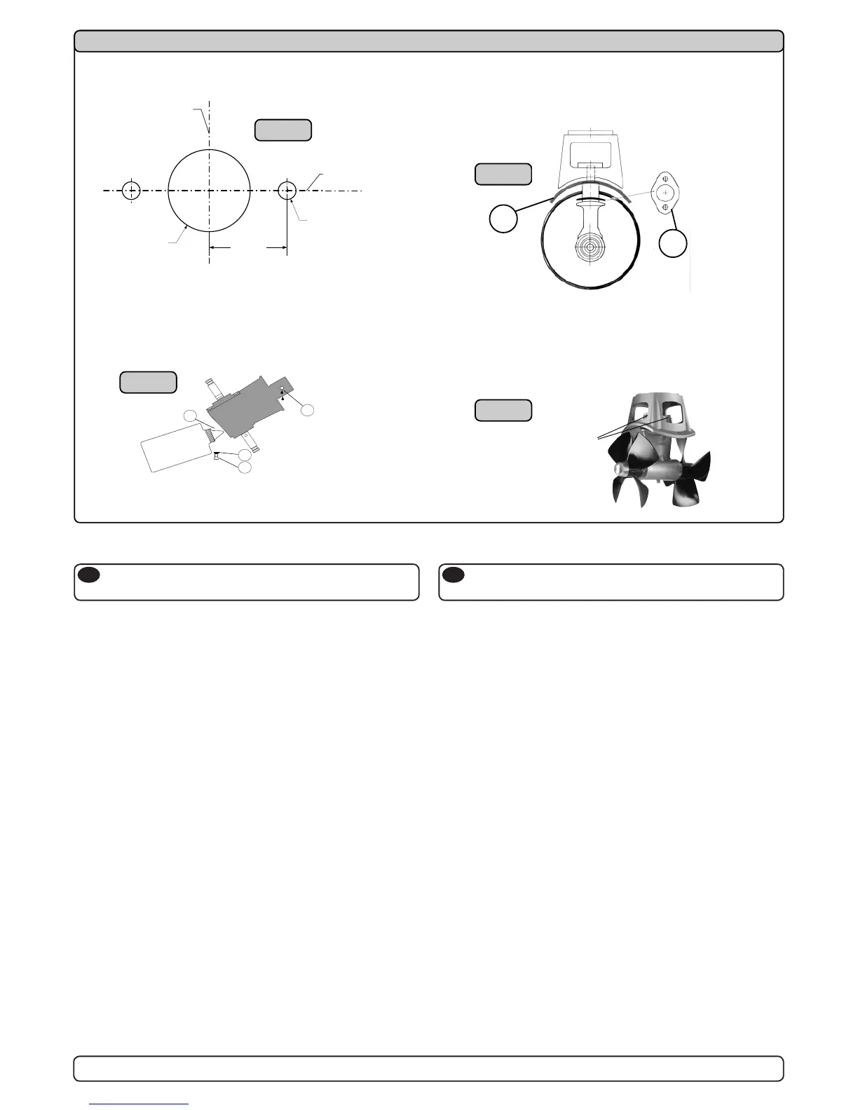
1. Mark the centreline of the tunnel and the boats. The propellers
and the lower unit must be completely inside the tunnel.
2. Use the gasket (A) to mark the centre of the holes and double
check the measurements.
NB ! All holes must be in-line with the tunnels' centreline for
precise installation, as the clearance between the propeller
and the tunnel is minimal.
3. There must be no casting where the motor bracket is to be
placed, as this will cause possible failure of the gearhouse.
The motor bracket must t steady on the tunnel, if the tunnel
is not smooth, all bumps or uneven parts must be grinded
smooth.
4. Drill the main hole and then the two screw holes.
5. Prell the gearhouse with gear oil type EP90 through the
oildrain screw (4). Make sure to get the copper gasket (3) on
again.
6. Try the lower-unit in the tunnel by using the gasket inside
the tunnel. Try on the propellers to make sure they are in the
middle of the tunnel and turn freely with the same clearing
from each blade to the tunnel. If the tunnel is not plain, use
some Sikaex or other sealant to ensure that no leakages
occur.
PS ! Make sure that no sealant gets in to the oil-holes (2).
7. Make sure that there is some oil or grease on the O-rings
in the motor bracket before mounting it together with the
gearhouse, as no lubrication could cause serious damage to
the O-rings.
8. Place the included rubber plate on the tunnel.
Getriebe und Motorhalterung
SP 550 HYD
D
Fitting gearhouse and motor bracket
SP 550 HYD
GB
15
1. Die Mittellinie von Tunnel und Boot markieren. Die Propeller und
die Getriebeeinheit dürfen nicht aus dem Tunnel herausstehen.
2. Die Löcher mit der Dichtung (A) markieren. Maße überprüfen!
NB ! Da der Abstand zwischen Propeller und Tunnel minimal ist,
müssen für eine präzise Installation alle Löcher auf der Mittel-
linie des Tunnels liegen.
3. Im Bereich der Motorhalterung darf kein Laminat auf dem
Tunnel sein, da dies zu einem Getriebeschaden führen kann.
Liegt die Motorhalterung nicht eben auf dem Tunnel auf, so
sind sämtliche Unebenheiten in diesem Bereich abzuschleifen.
4. Erst das Hauptloch, dann die beiden Bolzenlöcher bohren.
5. Das Getriebegehäuse mit Getriebeöl EP90 durch die Öffnung
der Ölablaßschraube (4) befüllen. Kupferdichtung (3) einsetzen.
6. Das Getriebegehäuse unter Verwendung der Dichtung in den
Tunnel einpassen. Den Propeller auf die Achse stecken;
dieser muß sich frei bewegen lassen und jedes Propellerblatt
muß den gleichen Abstand zum Tunnel aufweisen. Ist die
Tunnelinnenseite ungleichmäßig, etwas Sikaflex o.ä. auf-
tragen, damit keine undichte Stelle auftritt.
PS ! Die Durchgänge für das Öl (2) von Dichtmasse freihalten.
7. Etwas Öl oder Fett auf die O-ringe der Motorhalterung geben,
da diese sonst beim Zusammensetzen von Getriebegehäuse
und Motorhalterung beschädigt werden können.
8. Die beiliegende Gummiplatte auf dem Tunnel plazieren.
9. Das Getriebegehäuse durch das Hauptloch im Tunnel führen
und vorsichtig mit der Motorhalterung zusammenschieben.
10. Das Getriebegehäuse und die Motorhalterung mit Hilfe der bei-
den Bolzen verschrauben.
1. Mark the centreline of the tunnel and the boats. The propellers
and the lower unit must be completely inside the tunnel.
2. Use the gasket (A) to mark the centre of the holes and double
check the measurements.
NB ! All holes must be in-line with the tunnels' centreline for
precise installation, as the clearance between the propeller
and the tunnel is minimal.
3. There must be no casting where the motor bracket is to be
placed, as this will cause possible failure of the gearhouse.
The motor bracket must fit steady on the tunnel, if the tunnel is
not smooth, all bumps or uneven parts must be grinded smooth.
4. Drill the main hole and then the two screw holes.
5. Prefill the gearhouse with gear oil type EP90 through the oildrain
screw (4). Make sure to get the copper gasket (3) on again.
6. Try the lower-unit in the tunnel by using the gasket inside the
tunnel. Try on the propellers to make sure they are in the middle
of the tunnel and turn freely with the same clearing from each
blade to the tunnel. If the tunnel is not plain, use some Sikaflex
or other sealant to ensure that no leakages occur.
PS ! Make sure that no sealant gets in to the oil-holes (2).
7. Make sure that there is some oil or grease on the O-rings in the
motor bracket before mounting it together with the gearhouse,
as no lubrication could cause serious damage to the O-rings.
8. Place the included rubber plate on the tunnel.
9. Push the gearhouse through the main hole in the tunnel and
push the gearhouse and motor-bracket gently together.
10. Screw the lower unit and the motor-bracket together with the
two provided bolts.
SP 550 HYD
Getriebe und Motorhalterung
SP 550 HYD
D
Fitting gearhouse and motor bracket
SP 550 HYD
GB
SH100/185T - SP 220 HYD - SP 300 HYD - SP 550 HYD
2.4 - 2007
15
70,0mm
2 3/4"
Ø 17mm
2/3"
TUNNELS
CENTRELINE
BOATS
CENTRELINE
Ø 83mm
3 1/4"
Fig. 2
Fig. 3
G
E
A
R
O
I
L
E
P
9
0
3
4
1
 Loading...