SH100/185T- SH160/215T - SP 220 HYD - SP 300 HYD - SP 550 HYD 2.5 - 2008
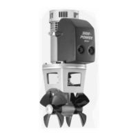
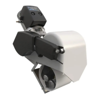
Einbau des Hydraulikmotors
D
1. Die 4 Bolzen in der Motorhalterung enfernen.
2. Die Antriebsachse im Getriebegehäuse und die Motorachse
so drehen, daß die elastische Kupplung dazwischen paßt.
3. Den Motor mit seiner Adapterplatte vorsichtig auf die Antriebs-
achse und die Motorhalterung aufsetzen.
4. Mit den 4 Bolzen Motor und Motorhalterung lose
verschrauben.
5. Mit den 4 Bolzen Motor/Adapterplatte und Motorhalterung
verschrauben. Anzugsmoment siehe oben.
6. Die Befestigungsschraube im unteren Teil der exiblen
Kupplung anziehen.
7. Überprüfen Sie, ob die beiden Bolzen, die den Motor an der
Adapterplatte befestigen. Anzugsmoment siehe oben.
Wir empfehlen auf die Befestigungsschraube im unteren Teil
der elastischen Kupplung Locktite o.ä. aufzutragen. Die obere
Befestigungsschraube ist bereits mit Locktite befestigt.
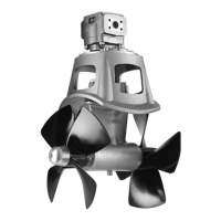
8. Überprüfen, ob sich die Propeller frei im Tunnel drehen
lassen. Aufgrund der Getriebeübersetzung und des Motors
sollte das Systemdies etwas schwergängig sein.
9. Installieren Sie einen Drainageschlauch.
In manchen Fällen, z.B. bei achem Rumpf oder im gerwerblichen
Einsatz (z.B. Fischfang) empfehlen wir, den Propeller durch
ein Gitter vor der Tunnelöffnung zu schützen (Fig. 1). Dieses
sollte auf ein Minimum beschränkt und so stromlinienförmig
wie möglich sein, da die Leistung des Thrusters bis zu ca. 10%
reduziert wird.
NB ! Wir empfehlen, auf das Getriebegehäuse Anti-Fouling
1. Remove the 4 bolts in the motorbracket.
2. Turn the driveshaft in the gearhouse and the motorshaft so
the key in the shaft and the keyway in the exible coupling are
in-line.
3. Slide the motor with its pretted adaptor plate onto the
driveshaft and the motor bracket gently.
4. Fasten the motor loosely to the bracket with the provided
bolts.
5. Fasten the adaptor plate rmly to the bracket with the
provided screws. Tighten the screws with the specied torque.
6. Tighten the set-screw in the lower part of the exible coupling.
7. Check the bolts holding the hydraulic motor to its adaptor
plate by tightening them with the speced torque.
It is advicable to apply a thread glue like Locktite or similar
on the lower set screw. The upper set screw is pretted with
locktite thread glue.
8. Check the system by turning the propeller, it will be a little
hard to turn (because of the gear reduction and the motor),
but you should be able to turn it by hand.
9. Make sure to install the drain hose.
In some cases (shallow installation or workboat / shingboat only)
we recommend to protect the propeller by mounting a grid in the
tunnel opening (Fig. 1). It is important to keep a grid to a mini-
mum and as streamlined for the thrusters waterow as possible,
as it can decrease the effect of the thrusters up to 10%.
NB ! Paint the gearhouse and propeller with antifouling for
pro-pellers to prevent growth of barnacles or similar which
Fitting the hydraulic motor
GB
20
Einbau des Hydraulikmotors
D
1. Die 4 Bolzen in der Motorhalterung enfernen.
2. Die Antriebsachse im Getriebegehäuse und die Motorachse
so drehen, daß die elastische Kupplung dazwischen paßt.
3. Den Motor mit seiner Adapterplatte vorsichtig auf die Antriebs-
achse und die Motorhalterung aufsetzen.
4. Mit den 4 Bolzen Motor und Motorhalterung lose verschrauben.
5. Mit den 4 Bolzen Motor/Adapterplatte und Motorhalterung
verschrauben. Anzugsmoment siehe oben.
6. Die Befestigungsschraube im unteren Teil der flexiblen
Kupplung anziehen.
7. Überprüfen Sie, ob die beiden Bolzen, die den Motor an der
Adapterplatte befestigen. Anzugsmoment siehe oben.
Wir empfehlen auf die Befestigungsschraube im unteren Teil
der elastischen Kupplung Locktite o.ä. aufzutragen. Die obere
Befestigungsschraube ist bereits mit Locktite befestigt.
8. Überprüfen, ob sich die Propeller frei im Tunnel drehen lassen.
Aufgrund der Getriebeübersetzung und des Motors sollte das
Systemdies etwas schwergängig sein.
9. Installieren Sie einen Drainageschlauch.
In manchen Fällen, z.B. bei flachem Rumpf oder im gerwerblichen
Einsatz (z.B. Fischfang) empfehlen wir, den Propeller durch ein
Gitter vor der Tunnelöffnung zu schützen (Fig. 1). Dieses sollte auf
ein Minimum beschränkt und so stromlinienförmig wie möglich sein,
da die Leistung des Thrusters bis zu ca. 10% reduziert wird.
NB ! Wir empfehlen, auf das Getriebegehäuse Anti-Fouling
aufzutragen. Nicht auf die Propellerachse, Zinkanoden oder
den Verschluß des Getriebegehäuses auftragen.
1. Remove the 4 bolts in the motorbracket.
2. Turn the driveshaft in the gearhouse and the motorshaft so the
key in the shaft and the keyway in the flexible coupling are in-line.
3. Slide the motor with its prefitted adaptor plate onto the
driveshaft and the motor bracket gently.
4. Fasten the motor loosely to the bracket with the provided bolts.
5. Fasten the adaptor plate firmly to the bracket with the provided
screws. Tighten the screws with the specified torque.
6. Tighten the set-screw in the lower part of the flexible coupling.
7. Check the bolts holding the hydraulic motor to its adaptor plate
by tightening them with the specfied torque.
It is advicable to apply a thread glue like Locktite or similar on
the lower set screw. The upper set screw is prefitted with
locktite thread glue.
8. Check the system by turning the propeller, it will be a little hard
to turn (because of the gear reduction and the motor), but you
should be able to turn it by hand.
9. Make sure to install the drain hose.
In some cases (shallow installation or workboat / fishingboat only)
we recommend to protect the propeller by mounting a grid in the
tunnel opening (Fig. 1). It is important to keep a grid to a minimum
and as streamlined for the thrusters waterflow as possible, as it
can decrease the effect of the thrusters up to 10%.
NB ! Paint the gearhouse and propeller with antifouling for pro-
pellers to prevent growth of barnacles or similar which would
reduce the performance dramatically. Do not paint the pro-
peller shaft, the zincanodes or the end face of the gearhouse.
Fitting the hydraulic motor
GB
Fig. 1
Bolt tightening forces:
2x bolts (M 12) holding motor to
adaptor plate: 57 Nm (42 lb/ft)
4x bolts (M 12) holding adaptor
plate to bracket: 57 Nm (42 lb/ft)
SH100/185T - SP 220 HYD - SP 300 HYD - SP 550 HYD
2.4 - 2007
20
SP 550 HYD
 Loading...