Installation and operating instructions MHS400 smart
05.2017 19
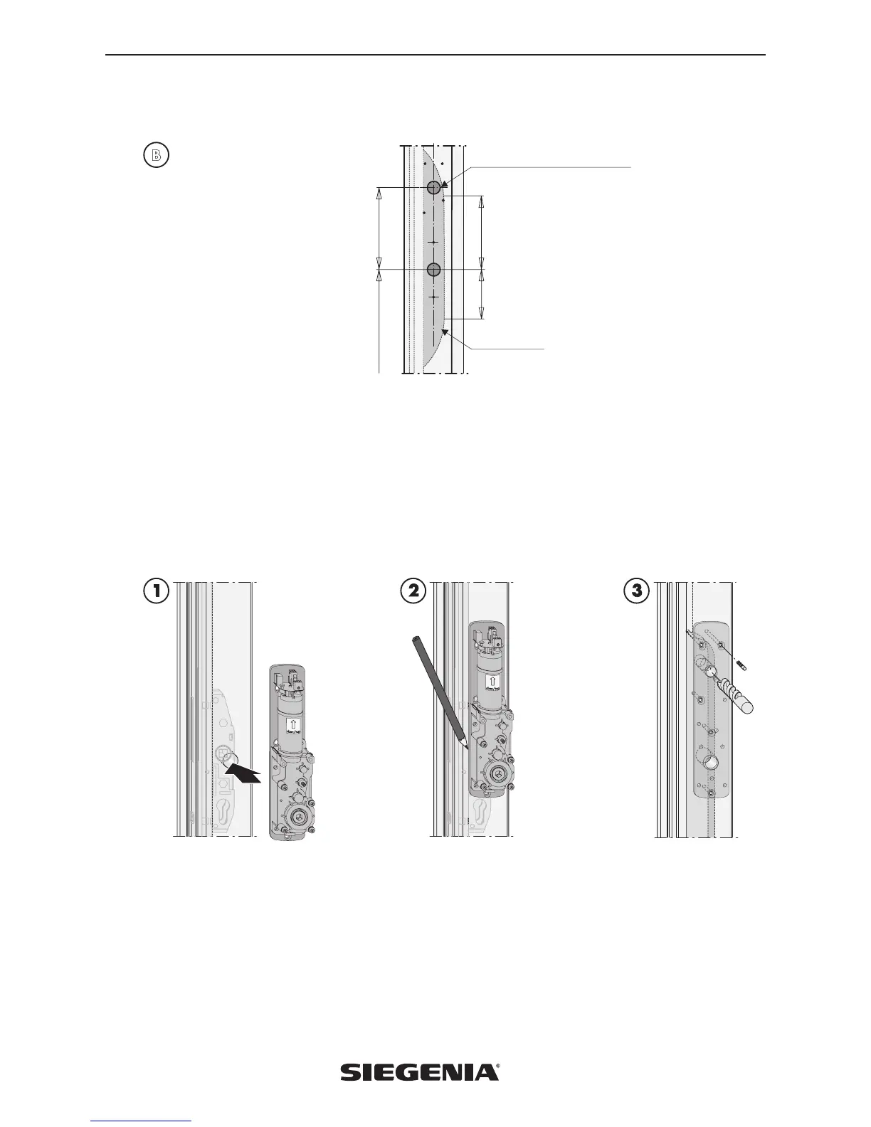
Option B — Extended gear recess on new lift & slide sash
70
120
100
B
All dimensions in mm
Ø 200 milling cutter
Handle position
Cable feed-through Ø 15 at front
1. Connect the lift drive HA to the fixing plate HA (do not screw)
2. Insert the square of the drive unit into the square mount on the lift & slide hardware gear and align on the lift & slide sash
(Fig. 1)
3. Mark the external edges of the fixing plate HA (Fig. 2).
4. Take the lift drive HA off the fixing plate HA.
5. Use the outline and drilled holes of the fixing plate HA for the marking out and drilling.
6. If necessary, clamp on the fixing plate HA as a drilling template and secure with 2 suitable screws.
7. Remove the lift-slide hardware gear.
8. Drill the cable feed-through at the front (Ø 15 mm) (Fig. 3).
Always assemble
the lift drive HA
upright
 Loading...