Product description
2.3 Basic versions
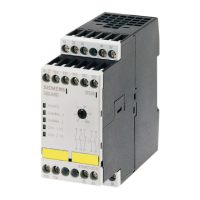
3TK2810-1 safety-related speed monitor
System Manual, 01/2011, 926246402000 DS 02
19
Terminal designations of the 3TK2810-1 speed monitor
Terminal Function
A1 24 V DC or 110 - 240 V AC/DC power supply
A2 Chassis ground/N
23/24 Safety-related output. Closed if speed is within permissible window
or power-up override time is running
13/14 Safety-related output. Closed if speed < speed limit or setup mode
has been selected (via EA1 and EA2)
15 Standstill signaling output
25 Speed signaling output
T1 Test signal channel 1
T2 Test signal channel 2
T3 Test signal channel 3
T4 Test signal channel 4
ST Start of the drive
RF1 Feedback circuit 1 input
RF2 Feedback circuit 2 input
P1 Input for position switch channel 1
P2 Input for position switch channel 2
MAG Input for magnet monitoring (contact closed/open when magnet
attracted/repelled)
EA1 setup speed/automatic speed channel 1 switchover
EA2 Setup speed/automatic speedchannel 2 switchover
U
3TK2810-1.A4.-0AA0 only: U1
Connection of proximity switch channel 1+2
GND
3TK2810-1.A4.-0AA0 only: U2
Connection of proximity switch channel 1+2
E1 Proximity switch 1 signal input
E2 Proximity switch 2 signal input
Interfaces of the 3TK2810-1 speed monitor
Interface Meaning
RJ45 Interface for connecting the encoder and for the copy function
Operator control elements of the 3TK2810-1 speed monitor
Element Meaning
Keys Navigation in the operator control menu / error acknowledgement

 Loading...