Operation
6.3 Configuring
3TK2810-1 safety-related speed monitor
48 System Manual, 01/2011, 926246402000 DS 02
6.3 Configuring
6.3.1 Configuration information
Mounting measuring sensors
Cross-circuits between the measuring sensors must be avoided by means of suitable cable
installation.
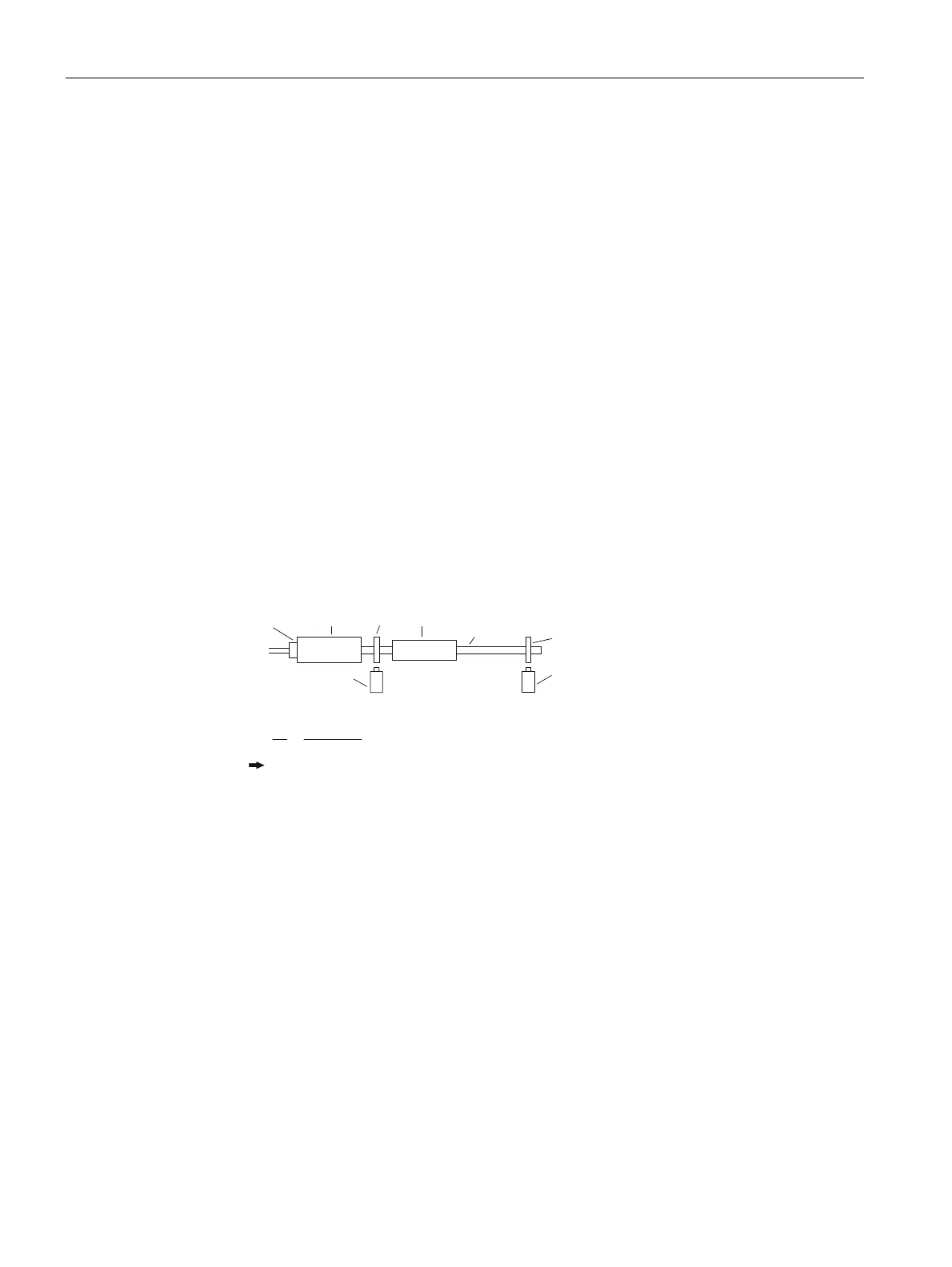
Transmission ratio or shaft fracture monitoring
In certain applications, it can be necessary to set a transmission ratio. The following
arrangement of the initiators or the encoder is necessary here:
● The speed to be monitored on the encoder or on initiator 1 (E1) must always be greater
than or equal to the speed to be monitored on initiator 2 (E2).
● The set speed limits on the display always refer to the encoder or to initiator 1 (E1) when
a transmission ratio is set.
● If the gear unit switched between E1 and E2 does not have an integer ratio, it can be
adjusted appropriately by modifying the resolution settings E1/E2 (pulses/rev. or mm).
(QFRGHUQೢ
,QSXWRQGLVSOD\UDWLR
0RWRU *HDUZKHHO
*HDUZKHHO
,QLWLDWRUQೣ
7UDQVPLVVLRQUDWLR
*HDUXQLW
,QLWLDWRUQೢ
6KDIW
¾ QೢQೣ [
(
(
¾ [
]%Q 8PLQQ 8PLQ
8PLQ
8PLQ
¾
Qೢ
Qೣ
QೢุQೣ
This arrangement is also used to detect a shaft fracture. If the measuring signals of the
measuring sensor do not agree with the measuring sensor on the shaft in accordance with
the ratio, the device switches immediately to a safe fault state.