Circuit diagrams
10.1 Circuit diagram
3TK2810-1 safety-related speed monitor
72 System Manual, 01/2011, 926246402000 DS 02
Application examples
7.
(
5-
$XWRPDWLFVHWWLQJ
21
6WDQGVWLOO
0RWRU
(QFRGHU
$ 7 5) 5) 7 ($ 3
$
7 ($ 3
8
*1'
(
(
7 67 0$*
/
1
6
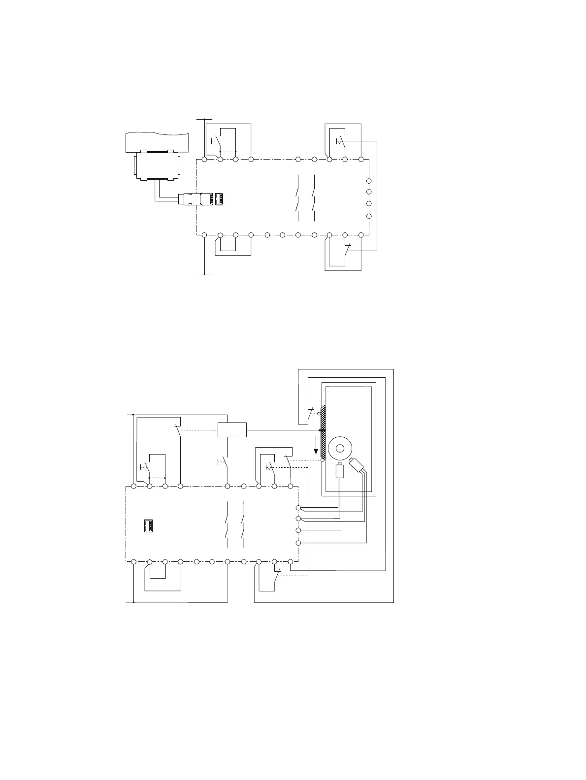
Speed and standstill monitoring using a suitable encoder, automatic mode; in the case of
manual start, on pushbutton at T4/ST; in the case of autostart, jumper at T4/ST; suitable up
to SIL 3, Performance Level e, SK 4 (a requirement for SK 4 is that in the case of longer
standstill times, a forced dormant error detection procedure t < 24 hrs is carried out).
7.
(
/
2Q
5-
$XWRPDWLFVHWWLQJ
6WDQGVWLOO
RSHQ
3URWHFWLYH
GRRU
FORVHG
'RRU
UHOHDVH
0DJQHW
$
1
7 5) 5) 7
($
3
$
7
67
6
67
(
(
($ 3
8
*1'
(
(
7 67 0$*
0
Two-channel speed and standstill monitoring using two NPN or PNP proximity switches,
automatic mode; protective door monitoring active; in the case of manual start, on
pushbutton at T4/ST; in the case of autostart, jumper at T4/ST; suitable up to SIL 3,
Performance Level e, SK 4 (a requirement for SK 4 is that in the case of longer standstill
times, a forced dormant error detection procedure t < 24 hrs is carried out).
Please read the note "Connecting the initiators" in chapter "Product-specific safety
inf
ormation (P
age 9)".
 Loading...