ణ ᄻْ
1. ߁ຎ
.....................................
2
2. Ҿጎ
.....................................
10
3. ֡ፕ
.....................................
20
4. ྼࢺ
.....................................
26
Contents page
1. Description
.......................................
2
2. Installation
.......................................
10
3. Operation
.........................................
20
4. Maintenance
....................................
26
൩ጀᅪۉഘยԢ࠲ࡋాևڦగၵևټ
ᆶླ၃ۉუă
փፏᆶ࠲Ҿඇ߾ፕڦڞሶࢅয়ߢLjࣷڞዂ
ჹዘڦටว๚ࠤ֎ׂ฿ă
ኻᆶຍຄଁĂࢃࢇ߭ڦටᇵ֍ీথةժ
֡ፕኄၵยԢࢅ࠲ጎዃă
ኄၵටᇵՂႷඇ௬ຄဒԨ๑ᆩ֩ాᆶڦ
ጀᅪ๚ၜࢅྼႪօየă
ኟඓںሏĂئ٪ĂҾጎᅜණኈں֡ፕࢅ
ྼࢺԍኤ࠲ጎዃຩ૧ࢅҾඇ߾ፕڦᅺ໎ă
࠲ጎዃፏቷူଚՔጚઠႜҾጎࢅ֡ፕ
ڦǖDIN VDE/IEC specifications: DIN VDE 0100-IEC
364; DIN VDE 0101; DIN VDE 0105; GB 3906,GB
11022ă
During operation of electrical equipment and switchgear,
certain parts are live and hazardous voltages therefore
present.
Non-observance of the safety instructions and warnings
can result in severe personal injury or property damage.
Only qualified personnel should work on or in the vicinity
of this equipment and switchgear.
Such personnel must become thoroughly familiar with all
warnings and maintenance procedures contained in these
operating instructions.
The successful and safe operation of this switchgear is
dependent on proper transport, storage, installation and
erection and also on diligent operation and maintenance.
Setting up and operation of this switchgear are
conditional on observance of the following
DIN VDE/IEC specifications: DIN VDE 0100-IEC 364;DIN
VDE 0101;DIN VDE 0105;GB 3906,GB 11022.
1. ߁ຎ ᄻْ
1.1 ᆌᆩݔྷ
..........................................................
2
1.1.1 ࠲ࡋڦ༬ኙ
...................................................
2
1.2 ࠓ
.................................................................
3
1.2.1 ႁࠓ
..........................................................
3
1.2.2 ۉഘย
..........................................................
3
1.2.2.1 ዷ࣮ୟ
..............................................................
3
1.2.2.2 ࣮ୟ
..........................................................
5
1.3 ߾ፕጒༀ
..........................................................
6
1.4 ຍຕ
..........................................................
7
1.1 ᆌᆩݔྷ
Ҿጎሞכฉ 3TL6 ኈথةഗᆩᇀ
• ߛუۉۯLjՎუഗă
• ഄೕݏࢇݴڦࢁLj૩සLjۉୗۉඹഗፇă
ᅜLj8BK30 ኈথةഗࡋᆩᇀ߾ĂᆳĂፈ༑ೝĂ
ۉበڪׇă
1.1.1 ࠲ࡋڦ༬ኙ
• ፌߛۉუٳ 12kV
• ڇజ၍
• ܮۨۉୁ
– ዷజ၍ፌٷٳ 4000A
– ݴኧజಇ 400A
• ߾ሰLjཚࡗ႙๕ᄓLjࢇҾጎᇀࢽాLjඓԍටวҾඇ
– ࡋా܆ႋߒӱۼঢ়ࡗాևۉࢷࠤቱᄓ
– ኈথةഗࢇݴۉᇸڦ֡ፕۼሞோ࠲Կ൧ူႜ
– ټۉጒڦ֪ᅜሞோ࠲Կ้ႜDŽDž
– ߳߰ᆩূຌ߰ӱ߰
1 Description page
1.1 Application
........................................................
2
1.1.1 Characteristic features of the switchpanels......2
1.2 Constrution
.......................................................
3
1.2.1 Mechanical construction
...................................
3
1.2.2 Electrical design
................................................
3
1.2.2.1 Main circuit
.........................................................
3
1.2.2.2 Auxiliary and control circuit
.................................
5
1.3 Mode of operation
............................................
6
1.4 Technical data
...................................................
7
1.1 Application
The vacuum contactors 3TL6 installed in the withdrawable
units are suitable for switching
• HV motors, transformers.
• Other loads with high switching frequency
e.g. arc furnaces or capacitors.
Withdrawable vacuum-contactor boards are thus used in
factories, refineries, drilling platforms, power stations, etc.
1.1.1 Characteristic features of the switchpanel
• Rated voltage up to 12kV.
• Single busbar.
• Rated current.
– of busbar up to 4000A
– of branch 400A
• Factory-built, type-tested for indoor installation
With metal-clad, compartmented panels
Safety of personnel ensured
– Sheet-steel enclosure tested for resistance to accidential
arcing
– Switching on/off the power by vacuum contactor
performed with the door closed
– Isolation from supply can be tested with the door
closed(option)
– Operating compartments segregated by metal partitions
֡ፕڦႠ / ྼႪ
– ྜኝڦဣཥ
– ௨ྼࢺߛუኈথةഗ
– ோڦഔဣཥڦ
࣍ৣԍࢺ
– ᆯᇀূຌހԿยLjᅺُஃሞࢆዖ߾ፕጒༀူۼԢ
ߛڦݞකీ૰
– ᇹጱܔක֫ڦႚׯᆶߛڦڸీ૰
༬༬ኙ
– ں௬ፌၭ
– ߛუথةഗߛუභഗጎሞכฉ
– כሞࡋా߾ፕ࿋ዃ / ࿋ዃኮᅎۯ
– ଆࡻڦࢻ࣑Ⴀ
– ᆩ܆ႋߒӱׯ߰ӱࢅோ
– ᅜሞࢫ௬থۉમ
– থᇑ 8BK20 ࠲ࡋጎ
1.2 ࠓ
1.2.1 ႁࠓ
ଇ߲ڇ܀ڦኈথةഗ࣮ୟҾಇሞཞᅃࡋ༹ాDŽມ࣮ୟDžǗ
3 4 ๖କࡋ༹ڦքዃLj߳߰Ljূຌ߰ӱோă
1.2.2 ۉഘย
1.2.2.1 ዷ࣮ୟ
ዷజಇDŽ4Lj 4Dž
ټኈথةഗڦכDŽ 5Dž
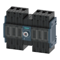
כฉጎᆯ 3TL6 ኈথةഗLjߛუභഗࢅଇፇةཀྵă
ᅜᆩᅃ T ႙դླྀĂઙכሞĐ߾ፕđࢅĐđଇ࿋ዃኮ
ᅎۯăٶோࢫLjכتᇀ࿋ዃ้Ljৢةཀྵᇑۯةཀྵ
ኮ߰ᆌӀ DIN VDE 0670Ljڼ 6 ևݴ /IEC298 ඓԍă
Operational reliability/maintenance
– Complete interlocking system
– Maintenance-free vacuum HV contactors
– Door included in the interlocking system
Environmental protection
– High pollution protection level by metal-enclosed design
for all operating status
– Insulators with high resistance to the formation of
pollution layers
Special features
– Minimum space requirement
– HV contactor and HVHRC fuses on the withdrawable unit
– Easy for move of withdrawable unit and between service
position disconnected position inside the panel
– Exchange of withdrawable units without any problems
– Partition plates and shutters are made of
sendzimir-galvanized sheet steel
– Cable connection from the rear side
– 8BK20 circuit-breaker panels can be arranged side by side
1.2Constrution
1.2.1Mechanical construction
Two individual panels are arranged in a common frame
(double panel); The panel layout, metal enclosure, partition
walls and shutters are shown in Figures 3 and 4.
1.2.2Electrical design
1.2.2.1Main circuit
Busbar (4,Figure 4)
Withdrawable unit including vacuum contactor (Figure 5)
The withdrawable unit is equipped with a 3TL6 vacuum
contactor, the contacts for accommodating the HV fuses.
The withdrawable unit can be moved between the service
and the disconnected positions with a hand crank. In the
disconnected positions by opened door the segregation
between the contact arms and the mating contacts is
assured in according to DIN VDE 0670,Part 6/IEC 298.
•
•
•
•
•
•
2Քጚࡋݛӄ Fig.2 Block diagram of standard panel
ᆩဦ၍ࣃڦᇮᅜඪ
Some of the parts drawn in thin lines
can be built on optionally.
Busbar
Branch bus
Contact on stationary part
Contact on withdrawable unit
Vacuum contactor
Earthing switch
Current transformer
HV fuse
Cable sealing end
Surge limiter