Do you have a question about the Siemens 8DJH Series and is the answer not in the manual?
Defines terms like DANGER, ATTENTION, and NOTE used in safety instructions.
Outlines general safety rules, PPE requirements, and compliance with local laws.
Describes the switchgear's correspondence to laws and its safety features.
Defines the qualifications and training required for personnel.
Lists typical uses and technological characteristics of the switchgear.
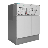
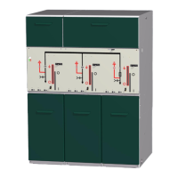
Provides an overview of panel modules, their widths, and configurability.
Details the various components of the switchgear, including switch-disconnectors.
Details the design and features of the three-position switch-disconnector.
Describes common and specific features of operating mechanisms.
Details the features and operating mechanisms of the vacuum circuit-breaker.
Explains mechanical and electrical interlocks for safe operation.
Describes the cable compartment covers and their removal conditions.
Details the features and specifications of the HV HRC fuse assembly.
Describes cable connections with bolted contacts for ring-main and circuit-breaker feeders.
Lists standards for current and voltage transformers.
Mentions customer-specific equipment installed in low-voltage compartments.
Lists different types of voltage detecting systems and their features.
Explains the function and features of the ready-for-service indicator.
Describes optional indicators for short-circuit and earth faults.
Lists standard and optional accessories like operating levers and keys.
Provides general electrical data including rated voltages, currents, and protection types.
Details switching capacities for general purpose, make-proof earthing, and fuse combinations.
Provides switching capacity and classification for disconnectors and earthing switches.
Details switching capacity, classification, and operating times of vacuum circuit-breakers.
Classifies the switchgear based on design, construction, and internal arc classification.
Lists relevant IEC/EN and VDE standards for switchgear and components.
Discusses EMC application standards and requirements for installation and maintenance.
Specifies the IP protection degrees for different parts of the switchgear.
Provides packing weights and details switchgear dimensions and gross weights.
States the permissible gas leakage rate.
Explains dielectric strength verification and altitude effects on insulation.
Provides recommendations for selecting HV HRC fuse-links for transformer protection.
Describes the information found on the rating plates, both front and inside.
States switchgear is maintenance-free; secondary equipment needs inspection.
Mentions difficulty in recommending spare parts due to optimized design.
Notes the presence of SF6 gas and its handling requirements.
Describes the environmentally compatible recycling of switchgear components.
Covers packing and checking for completeness and transport damage.
Details the different types of packing for transport units.
Outlines procedures for checking delivery completeness and identifying transport damages.
Provides guidelines for suitable storage rooms and conditions for transport units.
Details procedures and safety precautions for unloading and transporting switchgear.
Explains how to transport switchgear using cranes or fork-lift trucks while in original packing.
Describes the process of removing transport units from wooden pallets.
Explains how to attach and use crane eyes for lifting the switchgear.
Describes how to check the ready-for-service indicator and auxiliary switch.
Lists items to observe when preparing the foundation for switchgear installation.
Discusses basic requirements for achieving electromagnetic compatibility during switchgear erection.
Covers tools, preparations, and steps for installing the switchgear.
Lists standard tools and cleaning agents required for installation.
Outlines preparations and steps for installing the switchgear.
Provides guidelines for room planning, including arrangement types and dimensions.
Explains the standard and optional pressure relief directions.
Refers to dimension drawings for room and switchgear dimensions.
Details methods for fixing switchgear to foundations.
Describes standard and optional pressure relief configurations.
Refers to order documentation for switchgear dimensions.
Refers to page 48 for switchgear weight data.
Lists ways to fasten switchgear to the foundation for pressure resistance.
Details the process of fastening each panel to the foundation.
Explains how to mount the partition in the cable compartment.
Shows diagrams of floor openings and fixing points for standard panel blocks.
Illustrates versions with deep cable compartment covers and their dimensions.
Describes standard and optional pressure relief configurations.
Explains how to connect the switchgear to substation earth.
Discusses equipping manual mechanisms with motor operating mechanisms.
Provides attention points for connecting high-voltage cables.
Shows diagrams for cable connections for transformer feeders and ring-main/circuit-breaker feeders.
Details assembly operations for cable plug fastening.
Describes cable installation for switchgear with a pressure absorber.
Describes cable installation for switchgear with a pressure absorber up to 21 kA.
Explains mounting positions for cable-type current transformers.
Shows the principle of installing cable-type current transformers.
Details the steps for installing cable-type current transformers.
Describes wire routing for secondary equipment connections.
Instructs on noting and sending corrections to circuit diagrams.
Covers final tests, functional tests, and applying operating voltage.
Lists final tests to be performed after installation.
Details tests for mechanical and electrical functions before commissioning.
Outlines preparations for conducting a power-frequency voltage test.
Emphasizes the importance of instructing operating personnel.
Details steps for applying operating voltage and switching on feeders.
Provides information on internal arc classification and access regulations.
Identifies and labels indicators and control elements on the switchgear.
Provides safety warnings and checks before operating the three-position switch-disconnector.
Explains the standard and alternative methods for operating the three-position switch.
Describes protection tripping and re-establishing readiness for service.
Illustrates connecting and disconnecting feeders to the busbar using the three-position switch.
Shows the procedure for earthing a feeder using the three-position switch.
Shows the procedure for de-earthing a feeder.
Explains how to connect the transformer feeder to the busbar.
Details how to disconnect the transformer feeder from the busbar.
Describes the procedure for earthing the transformer feeder.
Details the procedure for de-earthing the transformer feeder.
Explains possible switching operations for the vacuum circuit-breaker.
Describes how to locally close the circuit-breaker.
Explains how to manually charge the spring energy store for the circuit-breaker.
Details the procedure for closing the three-position disconnector.
Details the procedure for opening the three-position disconnector.
Explains how to put the three-position disconnector into the EARTHED position.
Details how to deactivate the EARTHED position of the three-position disconnector.
Describes methods for verifying safe isolation from supply using indicators.
Provides information on replacing HV HRC fuse-links.
Explains how to remove the HV HRC fuse slide.
Details the procedure for replacing HV HRC fuse-links.
Describes how to insert the HV HRC fuse slide into the fuse box.
Explains how to close the HV HRC fuse compartment cover.
Introduces cable testing procedures.
Details the process of cable testing using cable plugs.
Lists maximum values for test voltages used in cable testing.
Outlines steps to be taken after completing the cable test.
Details the procedure for performing cable sheath testing.
| Insulation medium | SF6 gas |
|---|---|
| Enclosure | Metal-enclosed |
| Type | Gas-insulated switchgear |
| Operating mechanism | Spring mechanism |
| Dimensions | Varies depending on configuration |
| Weight | Varies depending on configuration |
