500-8067.9 * INSTALLATION AND OPERATING INSTRUCTIONS 8DJH * Revision 03 17
Description
Shunt release (f-release)
CLOSED/OPEN (optional)
Spring-operated/stored-energy mechanisms can be equipped with a magnetic tripping
coil (shunt release). Remote electrical tripping of the three-position switch-disconnector
is possible via the magnet coil, e.g. transformer overtemperature tripping.
To avoid thermal overloading of the shunt release in the event of a continuous signal that
may be applied, the shunt release is switched off via an auxiliary switch which is
mechanically coupled with the three-position switch-disconnector.
In transformer panels, continuity at the shunt release can only be tested when
the operating lever is removed.
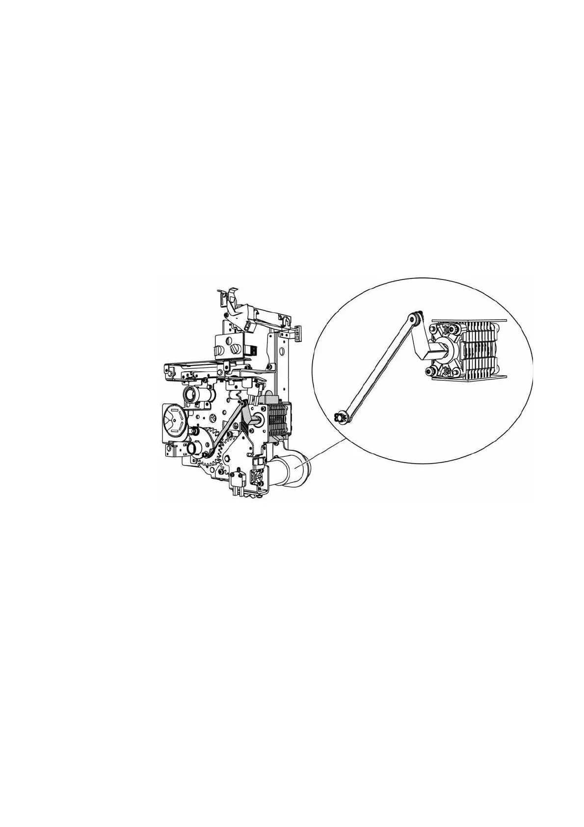
Auxiliary switch (optional) The operating mechanism of the three-position switch-disconnector can be optionally
equipped with an auxiliary switch for the position indication. A motor operating
mechanism is equipped with an auxiliary switch as standard.
• For switch-disconnector function: CLOSED and OPEN: 2 NO + 2 NC
• For earthing switch function: CLOSED and OPEN: 2 NO + 2 NC
Fig. 8: Auxiliary switch in the operating mechanism of the three-position switch-disconnector,
for example in the ring-main feeder
Wiring Auxiliary switches, motor operating mechanisms or shunt releases are wired to terminal
strips. The terminal strips are feeder-related and located over the operating mechanism
assembly of the feeder concerned. Customer-side cable routing is made from the side, if
required from above to the terminal strip arranged at the operating mechanism
assembly.

 Loading...


