Installation
92 Revision 03 * INSTALLATION AND OPERATING INSTRUCTIONS 8DJH * 500-8067.9
Ö Remove the two thread-ridging screws M6 of the cable compartment cover a.
Lift the cable compartment cover and remove it to the front..
Ö Remove the cross member s.
To do this, undo the 4 bolt-and-washer assemblies M8.
Ö Remove the front plate d of the pressure absorber.
To do this, undo the 6 bolt-and-washer assemblies M8.
Ö Take the front floor cover out.
Ö Lead the high-voltage cables into the cable compartment.
Ö Push rubber sleeves over the high-voltage cables.
Ö Push the high-voltage cables with the rubber sleeves into the cutout provided for this
purpose in the front floor cover.
Ö Refit the front floor cover observing that the floor cover fits correctly into the slot of
the rubber sleeve.
Ö Bolt the front floor cover to the foundation together with the switchgear frame using
three bolts.
Ö Mount the cross member, the front plate of the pressure absorber and the cable
compartment cover.
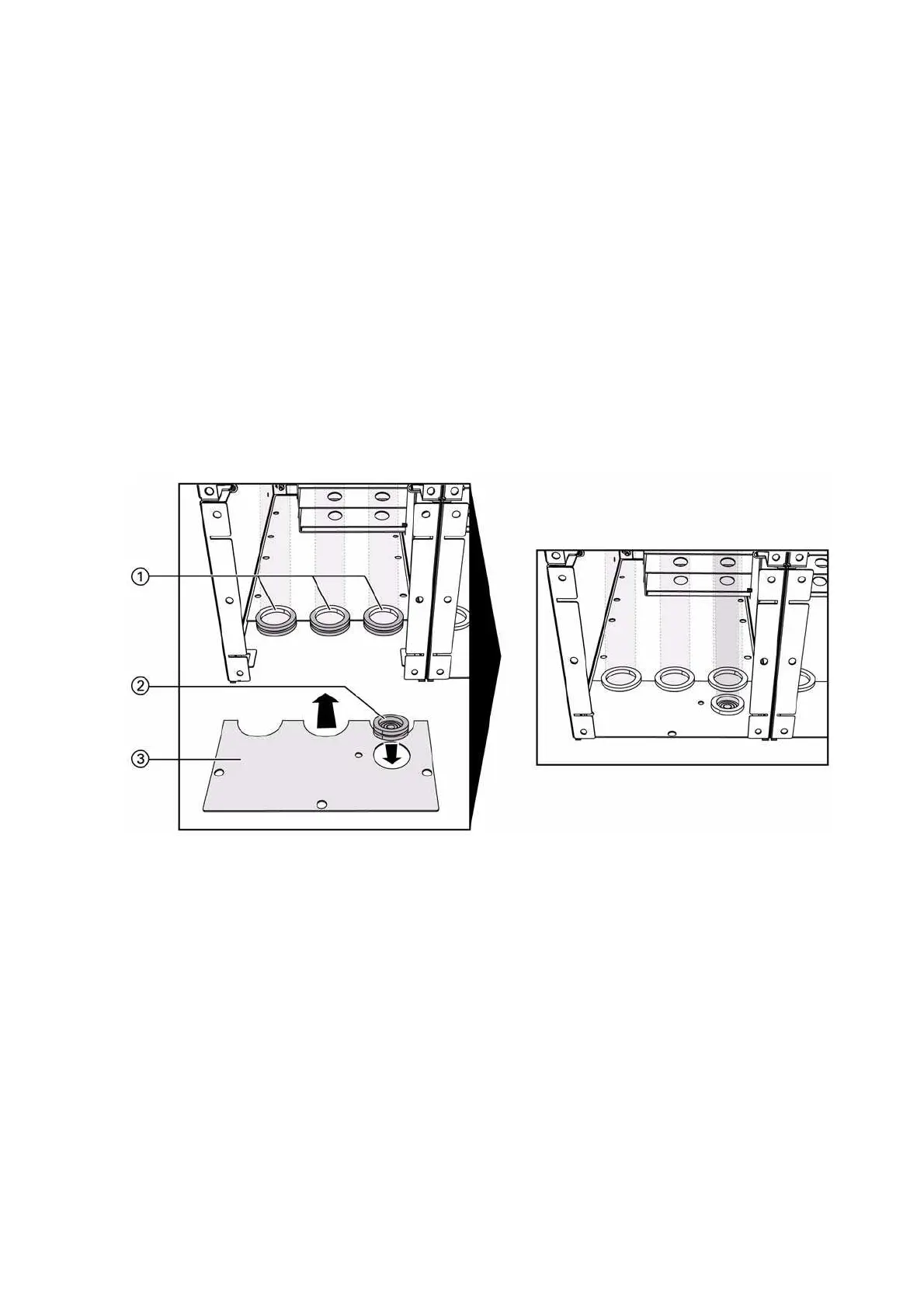
Fig. 65: Inserting the front floor cover and the rubber sleeves (switchgear up to 21 kA)
a
Rubber sleeves for cable entry (diameter 70 mm)
d
Front floor cover
s
If required, use rubber sleeves for control cables (diameter 56 mm) /
screened cable plugs

 Loading...


