Chapter 4 - Parameters and Menu Structure
Remaining time on timer (if active)
Remaining time on timer (if active)
Remaining time on timer (if active)
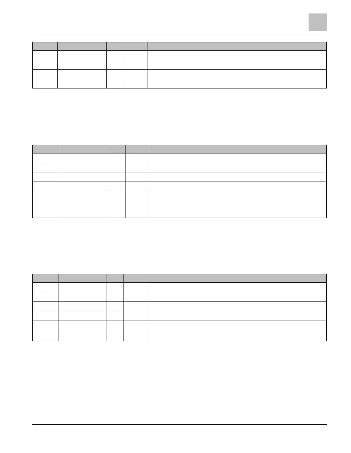
PID Controller 1 Monitoring (M2.4)
The PID Controller 1 monitoring values are the actual values of the first PID controller, which is used to control the
speed of the motor that is physically connected to the drive’s output. See
PID Controller 1
(M3.12).
The PID Controller 1 monitoring values are presented in the following table:
Table 8: PID1-Controller Value Monitoring.
Setpoint for the PID controller for the attached motor
Feedback for the PID controller for the attached motor
Error value of the PID controller for the attached motor
Output of the PID controller for the attached motor
0 = Stopped
1 = Running
3 = Sleep Mode
4 = In dead band
PID Controller 2 Monitoring (M2.5)
The PID Controller 2 monitoring values are the actual values of the second PID controller, which is used for external
devices that require PID loop control. See
PID Controller 2
(M3.13).
The PID Controller 2 monitoring values are presented in the following table:
Table 9: PID2-Controller Value Monitoring.
Setpoint for the PID controller for the external device (AO)
Feedback for the PID controller for the external device (AO)
Error value of the PID controller for the external device (AO)
Output of the PID controller for the external device (AO)
0 = Stopped
1 = Running
4 = In dead band
Multi-pump monitoring (M2.6)
The Multi-Pump monitoring values are the actual values related to the use of several drives/motors. See
Multi-Pump
(M3.14).
The Multi-Pump monitoring values are presented in the following table:






 To Next Page