Chapter 4 - Parameters and Menu Structure
NOTE:
The status of the Analog Outputs can be monitored in the Multimonitor (P2.1) view, or
in the I/O and Hardware (M5) menu.
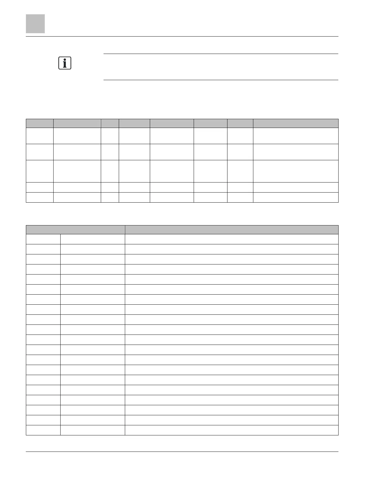
Slot A Basic (M3.5.4.1)
Table 38: Analog Outputs, Slot A (Basic).
Filter time of analog output signal
0 = No filtering
Settings:
0 = 0 Vdc/0 mA
1 = 2 Vdc/4 mA
Min Scale in process unit.
Max Scale in process unit
Table 39: Analog Output Functions.
AO is not used. 0 output.
AO is max. 10 Vdc or 20 mA output.
Track the Output Frequency based on 0 to Max Frequency (P3.3.2).
Track the Frequency Reference base on 0 to Max Frequency (P3.3.2).
Track the Motor Speed based on 0 to Motor Nom Speed (P3.1.1.3).
Track the Output Current based on 0 to Motor Nom Currnt (P3.1.1.4).
Track the Motor Torque based on 0 to TnMotor.
Track the Motor Power based on 0 to PnMotor.
Track the Motor Voltage based on 0 to VnMotor.
Track the DC Link Voltage based on 0 - 1000 Vdc.
Track the PID1 Output based on 0 - 100%
Track the PID2 Output based on 0 - 100%.
Track the Process Data In 1 where 5000 = 50.00%.
Track the Process Data In 2 where 5000 = 50.00%.
Track the Process Data In 3 where 5000 = 50.00%.
Track the Process Data In 4 where 5000 = 50.00%.
Track the Process Data In 5 where 5000 = 50.00%.
Track the Process Data In 6 where 5000 = 50.00%.
Track the Process Data In 7 where 5000 = 50.00%.
Track the Process Data In 8 where 5000 = 50.00%.





 To Next Page