4 Displays and Mode Selectors
B4A−22
CP 443-1 Advanced for Industrial Ethernet / Manual Part B4A
Release 01/2007
C79000-G8976-C193-06
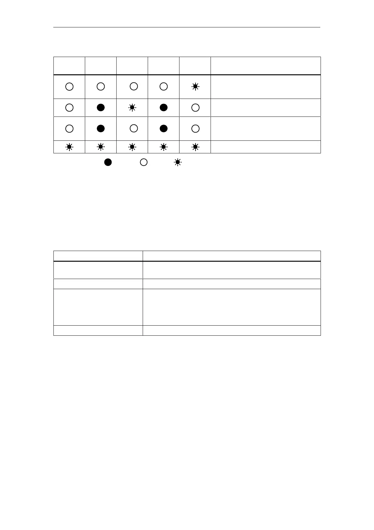
INTF LED
(red)
CP Operating ModeSTOP LED
(yellow)
RUN LED
(green)
BUSF LED
(red)
EXTF LED
(red)
Ready for firmware loading (this mode is
active for ten seconds following power up
when the mode selector is set to STOP)
RUN with external error; One or more IO
devices are not obtainable.
RUN with external error; Diagnostic
information from one or more IO devices
is available.
Module fault / system error
Legend: on off flashing
CP Communication Status
In addition to the LEDs that signal the CP mode, the front panel and the RJ-45
socket also include LEDs that provide information about the status of the CP
interface to Industrial Ethernet.
Table 4-1
LED
Meaning (LED on)
TXD LED (green) Flashing: CP is sending over Ind. Ethernet (note: in the current
version, it may also be permanently lit)
RXD LED (green) Flashing: The CP is receiving over Ind. Ethernet
LINK (green) Indicates an established connection to Ind. Ethernet:
S Not flashing = port set to 100 Mbps
S Flashing 0.5 Hz = port set to 10 Mbps
S Flashing 2 Hz = “Buzz” (flash test)
RX/TX-LED (yellow) Flashing: Port sending/receiving over Ind. Ethernet
Force Mode
You can control the mode of the CP 443-1 Advanced as follows:
S Mode selector
S STEP 7 / NCM S7 configuration software
To control the mode from STEP 7 / NCM S7, the mode selector must be set to
RUN.
 Loading...