Commissioning
4.2 Commissioning
Converter with Control Units CU230P-2; CU240B-2; CU240E-2
Getting Started, 11/2013, A5E32885834B AA
51
Table 4- 11 Digital outputs (relay outputs)
r52.2 - operation enabled (motor running)
r52.3 - fault active
r52.7 - alarm active
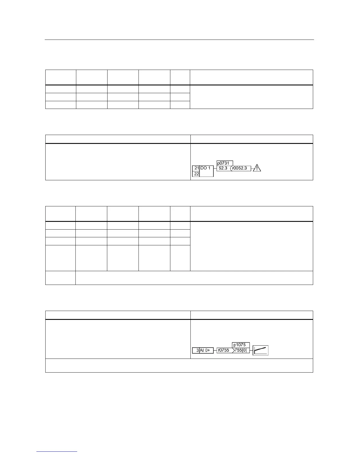
Table 4- 12 Changing the function of a digital output
1. Select the required function marked using a "BO" parameter.
2. Set the parameter p073x of the required digital output to the
value of the "BO" parameter.
Function
: Signal "Fault" on DO 1.
Setting
: p0731 = 52.3
Table 4- 13 Analog inputs and temperature sensors
0: Unipolar voltage input (0 V …+10 V)
1: Unipolar voltage input monitored (+2 V... +10 V)
2: Unipolar current input (0 mA …+20 mA)
3: Unipolar current input monitored (+4 mA …+20 mA)
4: Bipolar voltage input (-10 V …+10 V)
6: Ni1000 temperature sensor (-50°C … +150°C)
7: PT1000 temperature sensor (-50 …+250°C)
p0756 [3] - - 52 / 53 AI 3
p0755
Analog inputs, actual value in percent
Table 4- 14 Changing the function of an analog input
1. Select the required function marked using a "CI" parameter.
2. Set this parameter to the value of status parameter r0755.x of
the analog input.
Function
: AI 0 provides the setpoint for the PID
controller.
Setting
: p2253 = 55[0]
Use pa
rameter p0756[0] and the I/U switch on the front of the frequency converter to configure the analog input as voltage
or current input.

 Loading...


