FCM2041-U3 OPERATOR INTERFACE MANUAL | CHAPTER 3
MAINTENANCE MODE3-6
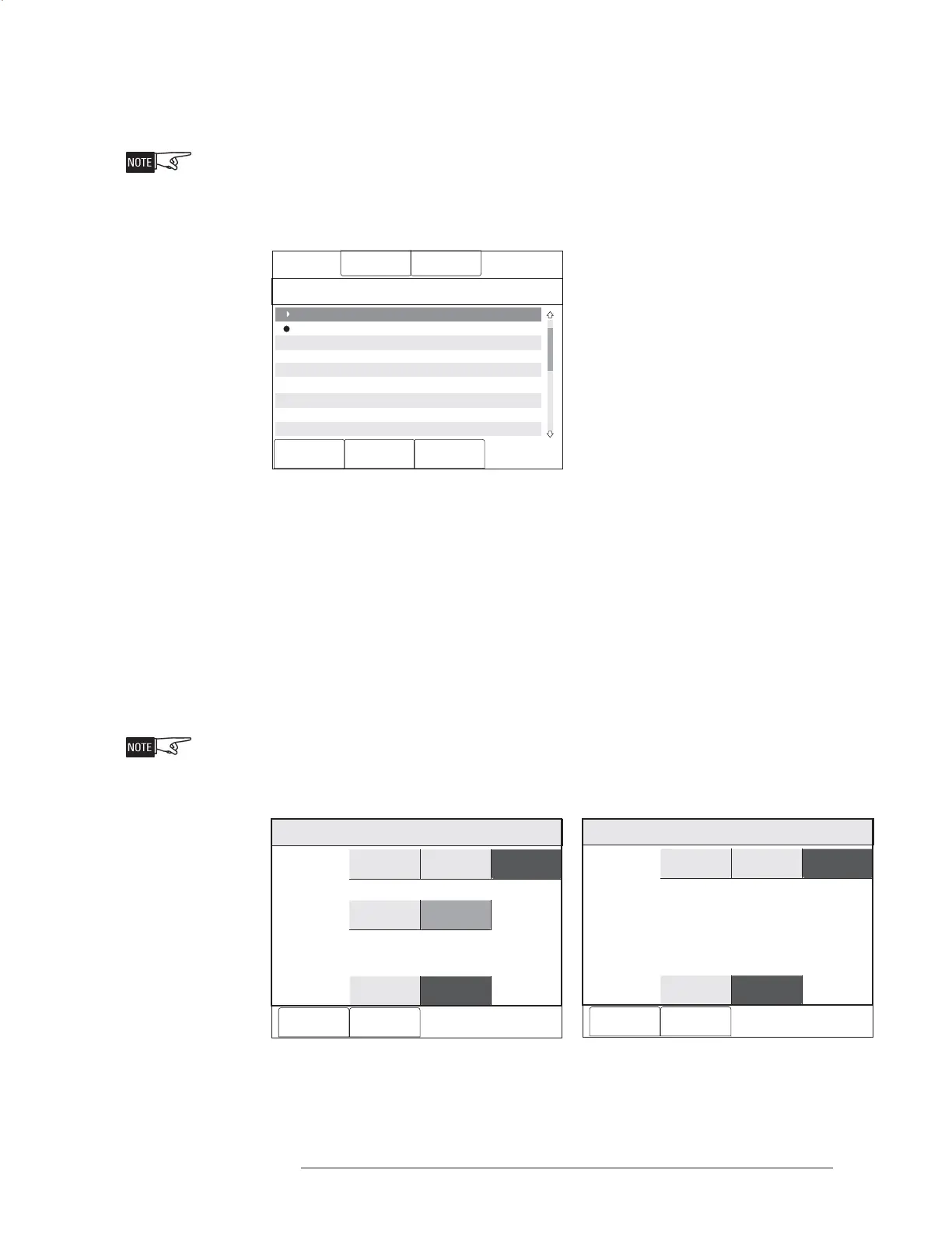
When the device is disarmed, a trouble reports on the system indicating exactly
what has been disarmed and the Partial System Disable LED glows steady yellow.
When you return to the system tree in Control/Maintenance, partially disarmed
modules/devices are graphically shown with the symbol in the far left column and
fully disarmed devices are shown with the symbol z in the far left column. (Refer to
Figure 3-8.) This screen is the same for both DLC, MLC and VPM (VESDA) devices.
Menu:Maint
PHY:FireFinder@1, DLC@1, HFP11@2
10:53
Category text information
Cancel
Control
2 HFP11 “HFP-11 at address 3-2”
3 HFP11 “HFP11 at address 3-3”
4 HFP11 “HFP11 at address 3-4”
5 HFP11 “HFP11 at address 3-5”
6 HFP11 “HFP11 at address 3-6”
7 HFPT11 “HFP11 at address 3-7”
8 HFPT11 “HFP11 at address 3-8”
9 HFPT11 “HFP11 at address 3-9”
10 HFPT11 “HFP11 at address 3-10”
Walktest
Geographic View GoTo
Figure 3-8
Disarmed Devices in Maintenance Menu System Tree
Outputs When the Outputs box is selected for DLC devices, the components section of the
screen displays the items that can be chosen. When the Outputs box is selected for
MLC devices, no components are available for individual selection—if Outputs is
selected, all MLC outputs are included. See Figure 3-9a for DLC devices and 3-9b for
MLC devices. Items that can not be chosen are grayed out. (In Figure 3-9a, LED is
grayed out.) Make a selection of the components you wish to disarm, then press the
OK soft key.
The Output Disarm feature is not available for VESDA detectors. The OI has no
control over the VESDA output relays.
Output
De-EnergizedEnergized
Apply To
Components
Menu:Maint:Control:Disarm:Settings
PHY: @1,FireFinder DLC@1, HFP11@2
Cancel OK
Inputs
LED
Devices
Relay 1
Outputs
Figure 3-9a Figure 3-9b
Disarm Outputs Settings - DLC Disarm Outputs Settings - MLC
Output
De-EnergizedEnergized
Apply To
Menu:Maint:Control:Disarm:Settings
PHY: @1,FireFinder MLC@2, FP11@2
Cancel OK
InputsDevices Outputs
 Loading...


