Building Technologies A6V10334410_h_en_--
Fire Safety 2015-09-29
3.2 Setup
Components
Overview
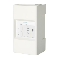
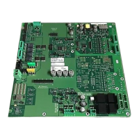
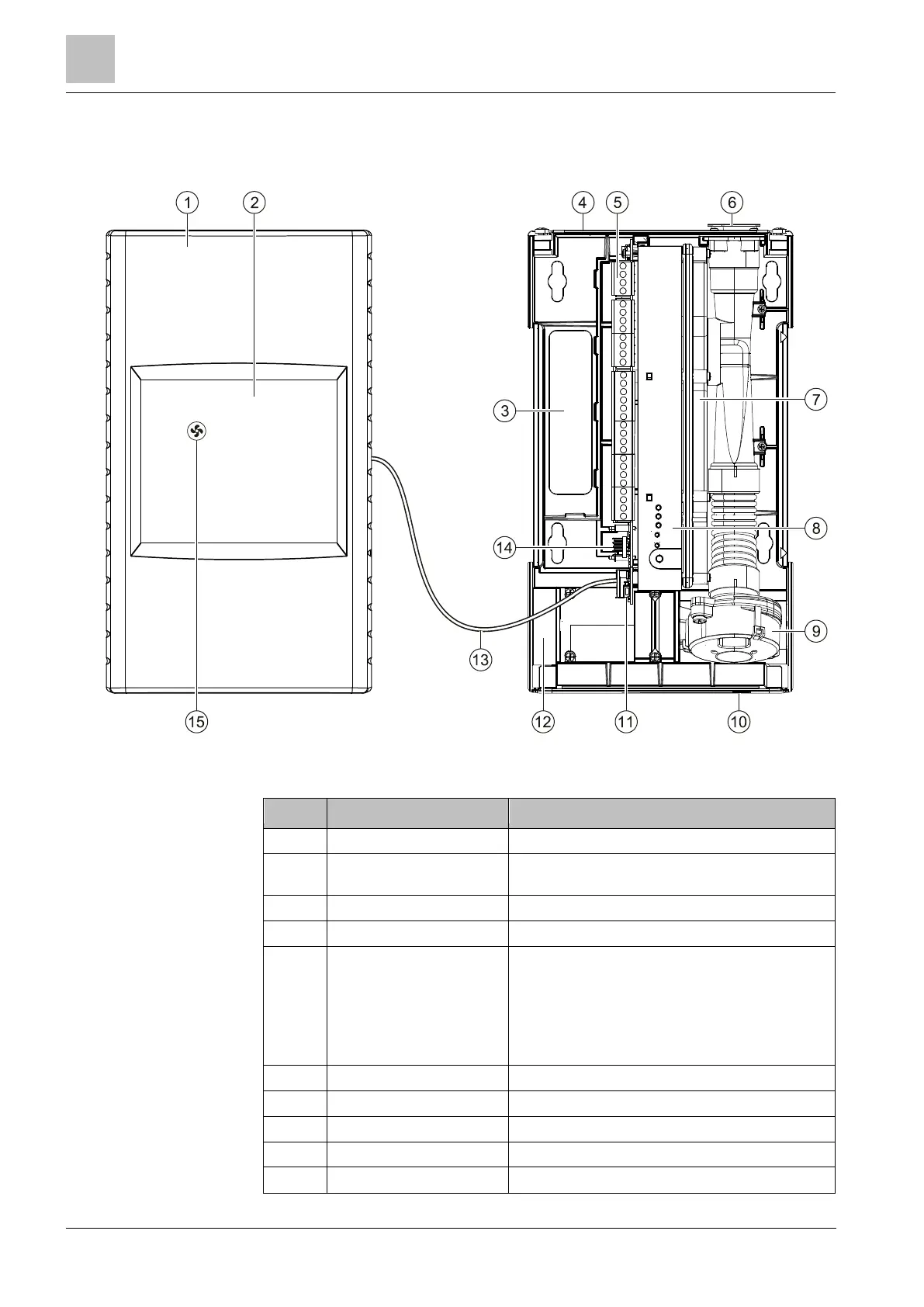
1 Housing cover -
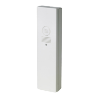
2 Front indicator Operating indicators and fault indicators,
connected to the interface card by a cable
3 Opening Cable entry
4 Back box Wall mounting with screws
5 Interface card Connections to external devices and signal
equipment. Depending on the version of the
aspirating smoke detector, not all connections are
available. If the aspirating smoke detector is
operated on a FDnet/C-NET detector line, certain
outputs are not active. See the chapter 'Function
[➙ 34]'.
6 Air inlet Pipe system connection
7 Detection chamber Smoke sensor with flow monitoring
8 Internal indicator Alarm indicator, activate normalization
9 Aspiration unit Fan for aspirating the air.
10 Type plate Relevant identification and detector data
 Loading...