Connection
6.1 Electrical connection
WOGeneric TEAAC / 2008
26 Siemens AG Operating Instructions 1.03 1RQ671...-Z
6.1.2 Terminal designation
The following definitions apply to the terminal designations of three-phase machines in
accordance with DIN VDE 0530 Part 8 or IEC / EN 60034-8:
Table 6-3 Terminal designations using the 1U1-1 as an example
1 U 1 - 1 Designation
x Index for pole assignment on pole-changing motors where applicable. A lower
index signifies a lower speed. Special case for split winding.
x Phase designation U, V, W (IEC) T1, T2, T3 (NEMA)
x Index for winding start (1) or end (2) or if there is more than one connection per
winding
x Additional index for cases in which it is obligatory to connect parallel power feed
cables to several terminals with otherwise identical designations
[ID: 332.02.01]
6.1.3 Direction of rotation
The technical specifications stipulate the following with respect to the motor connection:
● Direction of rotation
● The number and arrangement of the terminal boxes
● The circuit and connection of the motor winding
Direction of rotation
On motors which are only allowed to run in one direction, the rating plate shows an arrow
which indicates the permitted direction of rotation, and it also specifies the terminal
connections in the required phase sequence.
IEC NEMA
&ORFNZLVH
&RXQWHUFORFNZLVH
8 9 : 9 8 :
&ORFNZLVH
&RXQWHUFORFN
ZLVH
7
7
7
7
7
7
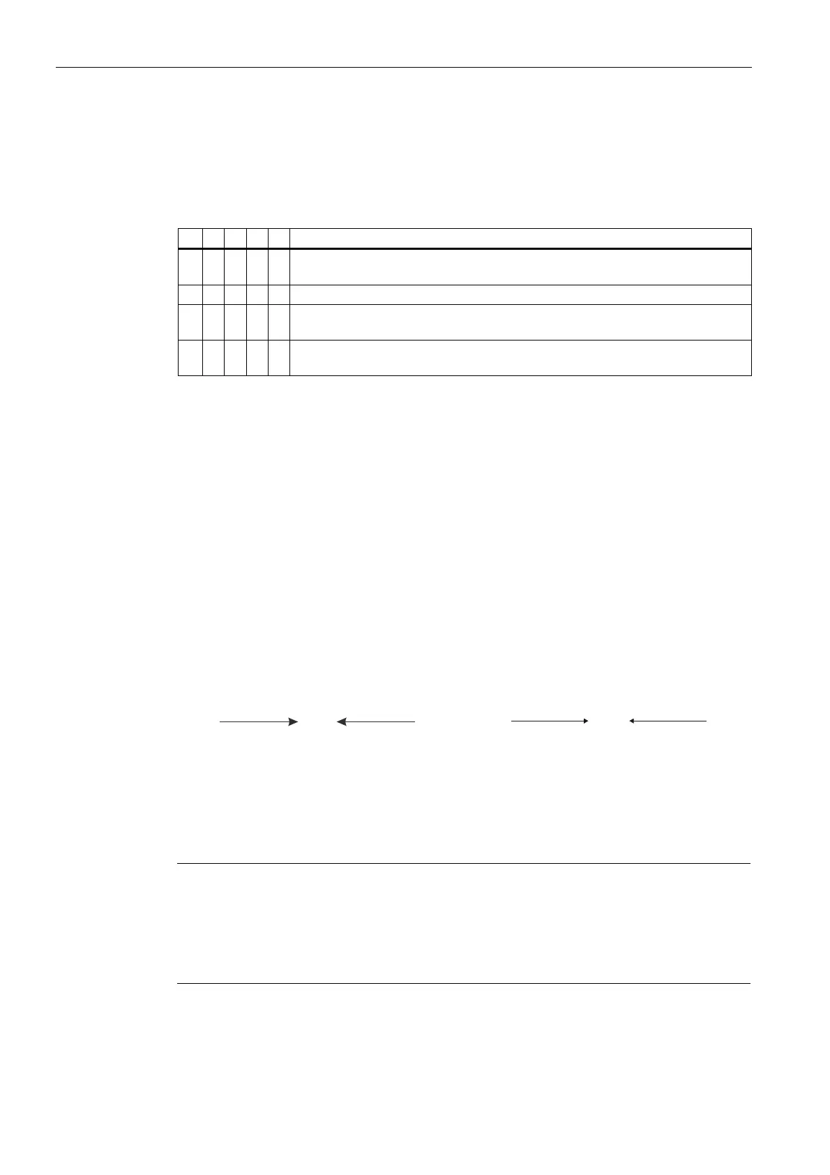
Direction of rotation of the motor when looking at the drive end
If you connect the power cables in the phase sequence L1, L2, L3 to U, V, W, the motor will
rotate clockwise. If two of the connections are swapped, then the motor will rotate
counterclockwise (e.g. L1, L2, L3 to V, U, W).
Note
If you want to run the motor in the opposite direction to the direction stated in the order,
please consult your contact partner at Siemens.
Rotational directions which may be required for application in a particular plant are not
shown on the rating plate. Please take these requirements into consideration when
connecting up the motor.