EasyManua.ls Logo

Siemens HCP User Manual

Siemens HCP
12 pages
To Next Page IconTo Next Page
Page #1 background imageLoading...
Page #1 background image
SiemensSiemens
SiemensSiemens
Siemens
Industry Industry
Industry Industry
Industry
,,
,,
,
Inc. Inc.
Inc. Inc.
Inc.
Building Building
Building Building
Building
TT
TT
T
ecec
ecec
ec
hnologies Dihnologies Di
hnologies Di
visionvision
visionvision
vision
P/N 315-034860-13
Intelligent Control Point
Installation Instructions
Model HCP
INTRODUCTION The Model HCP Intelligent Control Point from Siemens
Industry, Inc. provides remote, independent control of
any of the following:
1. A notification appliance circuit (NAC)
2. A telephone zone (XLS only)
3. A speaker zone (25V or 70.7V RMS) (XLS only,
FV2025/2050, FV922/924)
The HCP communicates through the DLC device loop
card of the FireFinder-XLS System, the FS-DLC device
loop card of the FS-250 System, the FC922/FV922,
FC2025/FV2025 periphery FCI2016 Board (250p)
detector circuits, and the FC2050/FV2050, FC924/FV924
FCI2017 periphery board (500p) detector circuits. Each HCP
uses one device address on the device loop.
PROGRAMMING Use the DPU Programmer/Tester to program and test the module.
The HCP may only be assigned addresses 1 to 60. It is recommended to program
the HCP devices first to ensure that enough addresses have been reserved for them.
Other devices may then be assigned to addresses in this range that were not
assigned to an HCP.
Disconnect wire at terminal 1 and 2 on TB1 before programming.
To set the HCP device address:
Plug the programming cable of the DPU Programmer/Tester into the two-
pin programming points on the HCP. (See Figure 1 for location.)
Set the device address for the HCP by following the instructions in the DPU
Programmer/Tester Manual, P/N 315-033260.
Each HCP can be assigned a custom message using either the Zeus Programming Tool
(XLS System), the FS-CT2 (FS-250 System), the FC2025/2050, FV2025/2050 FSX2002
Engineering Tool, or the FC922/924, FV922/924 FSX7212 Engineering Tool. Refer to
the Zeus Quick Start Manual, P/N 315-033875, or the FS-250 Programming Manual, P/
N 315-049403, as applicable.
PROGRAMMING
POINTS
DEVICE ADDRESS:
D
IS
C
O
N
NE
CT
W
IRE
AT TE
RM
INAL
"1"
&
"2"
SIEMENS INDUSTRY, INC.
C
A
U
T
IO
N
O
N
T
B
1
B
E
F
O
R
E
P
R
O
G
R
A
M
M
IN
G
FLORHAM PARK, NJ, 07932
INSTALLATION INSTRUCTIONS
T
B
2
O
N
B
A
C
K
S
ID
E
P/N 315-034860
SIEMENS
MODEL: HCP
T
B
1
O
N
B
A
C
K
S
ID
E
6
5
4
3
2
1
1
2
3
4
5
6
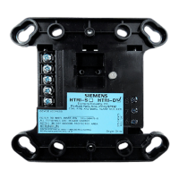
Figure 1
HCP Intelligent Control Point
Question and Answer IconNeed help?

Do you have a question about the Siemens HCP and is the answer not in the manual?

Siemens HCP Specifications

General IconGeneral
Product type designationHCP
CategoryControl Unit
ManufacturerSiemens
Supply voltage24 V DC
Number of axes6
InterfacesEthernet

Summary

INTRODUCTION

What is the Model HCP?

Describes the Model HCP's role in providing remote, independent control for various applications like NAC, telephone, and speaker zones.

HCP Communication Protocols

Explains how the HCP communicates through DLC device loop cards and specific periphery boards across different Siemens systems.

PROGRAMMING THE HCP

HCP Device Address Programming

Details the process of programming the HCP using the DPU Programmer/Tester and setting device addresses 1 to 60.

Custom Message Assignment

Outlines how to assign custom messages to HCP devices using specific Siemens programming tools like Zeus or FS-CT2.

SYSTEM COMPATIBILITY

WIRING GUIDELINES

Power Down and Wiring Precautions

Emphasizes removing system power before installation and adhering to wiring standards (18-12 AWG).

Device Loop Connections

Describes HCP communication via addressable device loops and connections to various system loop cards (DLC, FS-DLC).

HCP Power Supply Requirements

Details power supply requirements and connection points for HCPs in FireFinder-XLS and FS-250 systems.

DPU LOOP TESTING

HCP AS NOTIFICATION APPLIANCE CIRCUIT (NAC) MODULE

NAC Activation Principle

Explains using the HCP's polarity reversal for activating notification appliances and connecting output zones.

NAC Module Power and Output Limits

Covers the 24VDC power for supervision, maximum output load (1.5A), and trouble conditions for NAC module use.

HCP AS TELEPHONE ZONE MODULE

Telephone Zone Supervision and Power

Describes HCP use as a telephone zone module, power for supervision, and call-in detection on FireFinder-XLS.

Telephone Zone Wiring and Limitations

Details wiring the supervised telephone common talk riser and limitations on the number of phones off hook.

HCP AS SPEAKER ZONE MODULE (XLSV SYSTEM)

Speaker Zone Supervision and Audio Input

Explains 24VDC power for supervision, audio input requirements, and supervision when the zone is not active.

Speaker Zone Output and Performance

Discusses audio output limitations (25 watts) and decibel loss for wire gauge sizes in speaker zones.

HCP AS SPEAKER ZONE MODULE (FV2025/FV2050 OR FV922/FV924 SYSTEM)

Speaker Zone Input and System Integration

Details 70.7V/25V RMS audio input requirements, supervision, and degrade mode functionality for these systems.

Speaker Zone Wire Loss Analysis

Presents figures showing approximate speaker zone wire loss (dB) for 70.7V and 25V options based on wire gauge and length.

UNIT MOUNTING INSTRUCTIONS

Pre-Mounting Programming Requirement

Advises programming the HCP before mounting it to the switchbox for proper installation.

Electrical Box and Extension Requirements

Specifies UL listed electrical box types and dimensions required for HCP installation, including extensions.

ELECTRICAL RATINGS

CYBER SECURITY DISCLAIMER

Related product manuals