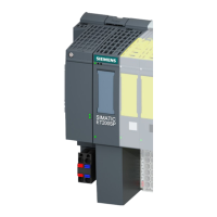
Functions of the IM 151-7 CPU
8-4
ET 200S IM 151-7 CPU Interface Module
A5E00058783-04
8.2 The mode selector and LEDs
Mode selector
The mode selector of the IM 151-7 CPU is designed as a 3-step toggle switch (see
below):
RUN
STOP
MRES
Figure 8-1 Mode selector
Positions of the mode selector
The positions of the mode selector are explained in the order in which they are
arranged on the IM 151-7 CPU.
Table 8-2 Positions of the mode selector
Position
Description Description
RUN RUN mode The CPU processes the user program.
STOP STOP mode The CPU processes no user program.
Programs can:
Be read out from the CPU using a PD (CPU PD)
Transferred to the CPU (PD CPU)
MRES Reset CPU
memory
Momentary-contact position of the mode selector for resetting the
CPU memory.
You must adhere to a specific sequence when resetting the CPU
memory using the mode selector (see Section 7.2)

 Loading...


