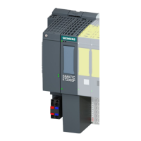
ET 200S in the PROFIBUS Network
4-8
ET 200S IM 151-7 CPU Interface Module
A5E00058783-04
4.3 PROFIBUS address
Features
Use the PROFIBUS address to specify the address at which the IM 151-7 CPU is
contacted on the PROFIBUS-DP.
Prerequisites
The permitted PROFIBUS-DP addresses are 1 to 125.
Each address can be allocated only once on the PROFIBUS-DP.
Startup without DP configuration on the Micro Memory Card (MMC) (initial
startup)
Following POWER ON, the coexistent interface on the IM 151-7 CPU powers up
as an MPI interface with the address 2, HSA 31 and 187.5 kBaud. The I slave
functionality of the IM 151-7 CPU is not yet available. All PD functions listed in
Section 4.4 are possible with the interface.
Several ET 200S units with IM 151-7 CPUs as I slaves on one PROFIBUS network
must be commissioned step by step. After each individual IM 151-7 CPU has been
switched on, STEP 7 must be used to transfer a configuration with DP address to
the IM 151-7 CPU.
Note
The bus parameters are retentive, i.e.bus parameters that have been configured
(e.g. address, transmission rate) are retained
with POWER OFF
if there is no longer a configuration on the IM 151-7 CPU (e.g. after SDBs have
been deleted or following POWER ON without MMC)
Startup with DP configuration on the Micro Memory Card (MMC)
As soon as a DP configuration has been downloaded to the IM 151-7 CPU, the
data stored on the MMC is used on startup.
Following POWER ON, the IM 151-7 CPU as the I slave powers up with the
configured address and waits for parameter assignment by the DP master.
As active PROFIBUS node, the IM 151-7 CPU adopts the configured transmission
rate.
As passive PROFIBUS node, the IM 151-7 CPU searches for the transmission
rate.

 Loading...


