216/327
Building Technologies Basic Documentation LMV5... CC1P7550en
13 Mounting , electrical installation and service 22.05.2018
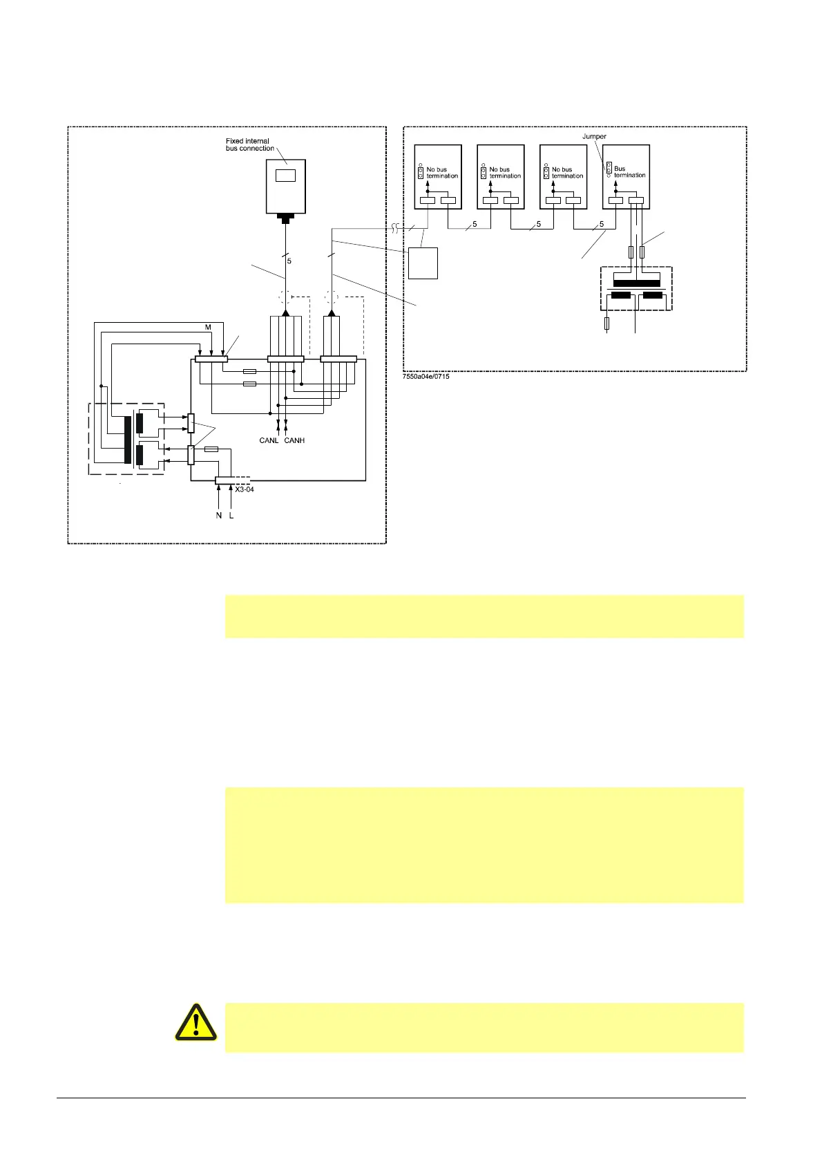
LMV5 in the control panel, actuator on the burner; CAN bus cable LMV5 ↑ last
actuator >20 m
SA4 - SA1: 20 m
AGG5.641
LMV5...- SA1: 75 m
AGG5.641 or
AGG5.631
Only
CANH
CANL
GND
Max. cable length
from power supply
of actuator 3 m
RAST3,5
transformer
X52
Power
transformer 1
AGG5.2xx
AC1 12 V
LMV5... basic unit
F1 T6.3
X10-01
F3 T4
X51
Max. bus cable length
LMV5...-AZL51...: 5 m
AGG5.631
Control cabinet
SA 4
SA 3
SA 2
SA 1
N
AC2 12 V
Power line
max. 3 m
AC2 12 V
AZL5...
AGG5.2xx
Burner
3
12 V
0 V
0 V
12 V
230 V
12 V
0 V
Figure 95: LMV5 in the control panels, actuator on the burner; CAN bus cable LMV 5
↑
last actuator
>20 m
Β
Notes on example 2!
Total length of CAN bus cable ′100 m
Whenever the distance between the LMV5 and the last actuator exceeds 20 m, or if
more than 4 SQM45 are used on the burner (see chapter Determination of maximum
CAN cable length AGG5.6), a second transformer is required for powering the
actuators.
In that case, transformer 1 powers the LMV5 and the AZL5 (control panel). Transformer
2 powers the actuators (burner).
Β
Note!
With the CAN bus cable connections from the LMV5 (control panel) to the first actuator
(burner), the 2 voltages AC1 and AC2 on the LMV5 side must not be connected and
only cables CANH, CANL and GND (+shielding) are to be connected to the first
actuator (burner).
In that case, the actuators must be powered by a second transformer which is to be
located near the actuators.
The power from that transformer (lines AC1, AC2, GND) must be fed to the actuator
(ACT4 in the example above) and then connected through via bus cable AGG5.641 to
all the other actuators.
The fuses required for transformer 1 are accommodated in the LMV5.
Caution!
For transformer 2, the 3 fuses (F T2 and 2*F T4) must be located close to the
transformer.
Example 2
 Loading...