217/327
Building Technologies Basic Documentation LMV5... CC1P7550en
13 Mounting , electrical installation and service 22.05.2018
Installation of all components in the burner; CAN bus cable LMV52 ♠ last
actuator >20 m with 6 actuators and PLL52
RAST3,5
Trafo
X52
Power transformer 1
AGG5.2xx
AC1 12 V
LMV52... basic unit
F1 T6,3
F3 T4
max. bus cable lengt h
LMV5...-AZL51...: 60 m
AGG5.631
Sub-D
connector
AZL5...
Power line
max. 3 m AC2 12 V
X3-04
max. bus cable length
LMV5x...-SQM4x...: 20 m
AGG5.641
SA 4
SQM45...
SA 3
SQM45...
SA 2
SQM45...
SA 1
SQM45...
F2 T4
Only
CANH
CANL
GND
SA 6
SA 5
PLL52...
F T2
N
AC2 12 V
Free
AGG5.2xx
0 V
12 V
0 V
0 V
12 V
230 V
12 V
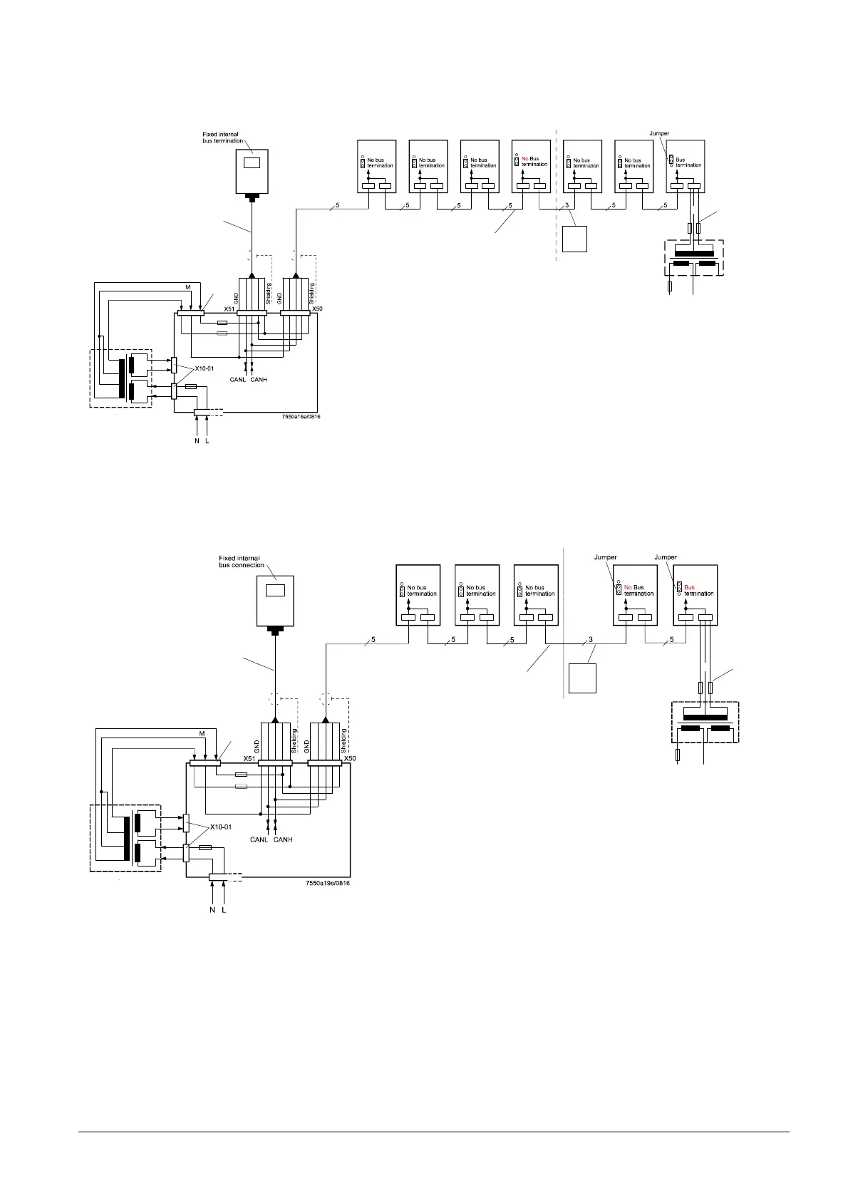
Figure 96: Installation of all components in the burner; CAN bus cable LMV52
♠
last actuator >20 m
with 6 actuators and PLL52
Installation in the control panel, actuator on the burner and on the boiler;
CAN bus cable LMV52 ♠ last actuator >25 m with 4 actuators and PLL52
RAST3,5
Transformer
X52
Power
transformer 1
AGG5.2xx
AC1 12 V
LMV52... basic unit
F1 T6,3
F3 T4
Max. bus cable length
LMV5...-AZL51...: 60 m
AGG5.631
Sub-D
connector
AZL5...
Power line
max. 3 m
AC2 12 V
X3-04
Max. bus cable length
LMV5x...-SQM4x...: 20 m
AGG5.641
SA 3
SQM48...
SA 2
SQM45...
SA 1
SQM45...
F2 T4
Only
CANH
CANL
GND
SA 4
SQM48...
of actuator 10 m
PLL52...
N
AC2 12 V
AGG5.2xx
12 V
0 V
0 V
12 V
230 V
12 V
0 V
Figure 97: Installation in the control panel, actuator on the burner and the boiler; CAN bus cable LMV52
♠
last actuator >25 m with 4 actuators and PLL52
Example 3a
Example 3b
 Loading...