67
LOGO! Manual
A5E00067781 01
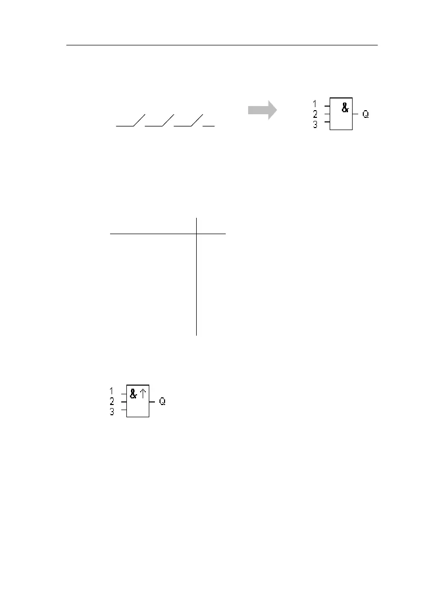
4.2.1 AND
The series connection of a number of nor-
mally open contacts is represented in a
circuit diagram as follows:
Symbol in LOGO!:
The output of the AND only adopts the state 1 if all the in-
puts have the state 1 (i.e. they are closed).
If an input pin of this block is not wired (x), then the follow-
ing applies to the input: x = 1.
Logic table for AND
123Q
0 0 0 0
0010
0100
0110
1000
1010
1100
1111
4.2.2 AND with RLO Edge Detection
Symbol in LOGO!:
The output of AND with RLO edge detection only adopts
the state 1 when all inputs have the state 1 and at least
one input had the state 0 in the previous cycle.
If an input pin of this block is not wired (x), then the follow-
ing applies to the input: x = 1.
LOGO! Functions
 Loading...