EasyManua.ls Logo

Siemens MICROMASTER Vector

Siemens MICROMASTER Vector
79 pages
To Next Page IconTo Next Page
Loading...
© Siemens plc 1999 G85139-H1751-U529-D1
4/8/9
9
Contents
SAFETY INSTRUCTIONS ............................................................... 4
1. OVERVIEW .............................................................................. 6
2. INSTALLATION - MICROMASTER Vector........................... 12
3. INSTALLATION - MIDIMASTER Vector ............................... 25
4. CONTROLS AND BASIC OPERATION ................................ 32
5. OPERATING MODES ............................................................ 36
6. SYSTEM PARAMETERS....................................................... 41
7. FAULT AND WARNING CODES........................................... 65
8. SPECIFICATIONS.................................................................. 67
9. SUPPLEMENTARY INFORMATION ..................................... 73
MICROMASTER Vector
MIDIMASTER
Vector
Operating Instructions
Question and Answer IconNeed help?

Do you have a question about the Siemens MICROMASTER Vector and is the answer not in the manual?

Siemens MICROMASTER Vector Specifications

General IconGeneral
BrandSiemens
ModelMICROMASTER Vector
CategoryMedia Converter
LanguageEnglish

Summary

Safety Instructions

General Safety Warnings

Important warnings and precautions for safe operation and installation.

1. OVERVIEW

1.2 Wiring Guidelines to Minimize EMI

Recommendations for wiring to reduce electromagnetic interference (EMI).

1.3 Electrical Installation - General Notes

General notes regarding electrical installation and power supply.

2. INSTALLATION - MICROMASTER Vector

2.1 Mechanical Installation

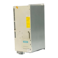
Procedures and considerations for physically mounting the MICROMASTER Vector unit.

2.2 Electrical Installation

Details on connecting power and control cables for the inverter.

2.2.1 Power and Motor Connections - Frame Size A

Connecting power and motor cables for Frame Size A MICROMASTER Vector units.

2.2.2 Power and Motor Connections - Frame Size B

Connecting power and motor cables for Frame Size B MICROMASTER Vector units.

2.2.3 Power and Motor Connections - Frame Size C

Connecting power and motor cables for Frame Size C MICROMASTER Vector units.

2.2.4 Control Connections

Instructions for making control connections to the MICROMASTER Vector.

2.2.5 External Motor Thermal Overload Protection

How to connect a PTC temperature sensor for motor overload protection.

3. INSTALLATION - MIDIMASTER Vector

3.1 Mechanical Installation

Procedures for physically mounting the MIDIMASTER Vector units.

3.2 Electrical Installation

Details for electrical installation and wiring of the MIDIMASTER Vector.

3.2.1 Power and Motor Connections

Connecting power and motor cables for MIDIMASTER Vector units.

3.2.2 Control Connections

Instructions for making control connections to the MIDIMASTER Vector.

3.2.3 Motor Overload Protection

Measures for protecting the motor against overheating.

4. CONTROLS & BASIC OPERATION

4.1 Controls

Description of the front panel controls and their functions.

4.2 Basic Operation

General guidance on operating the inverter and performing initial tests.

4.2.3 Basic Operation - 10 Step Guide

A step-by-step guide for basic setup and operation of the inverter.

5. OPERATING MODES

5.3 Motor Control Modes

Explanation of different motor control modes available in the inverters.

5.7 Closed Loop Control

Description of the PID control function for closed-loop applications.

6. SYSTEM PARAMETERS

Resetting to Factory Defaults

Procedure for resetting all parameters to factory default settings.

P051 Selection control function, DIN1

Configures DIN1 for selection control or fixed frequency.

P077 Control mode

Selects the motor control mode (V/f, FCC, Vector).

P088 Automatic calibration

Performs automatic measurement of motor stator resistance.

P006 Frequency setpoint source selection

Selects the source for the frequency setpoint (digital, analogue, etc.).

P052 Selection control function, DIN2

Configures DIN2 for selection control or fixed frequency.

P023 Analogue input 1 type

Configures the type of signal for analogue input 1.

P053 Selection control function, DIN3

Configures DIN3 for selection control or fixed frequency.

P386 Sensorless vector speed control loop gain - proportional term

Sets the proportional gain for sensorless vector control.

7. FAULT AND WARNING CODES

7.1 Fault Codes

Lists fault codes, their causes, and corrective actions for the inverter.

7.2 Warning Codes

Lists warning codes, their causes, and corrective actions.

9. SUPPLEMENTARY INFORMATION

9.3 Electro-Magnetic Compatibility (EMC)

Information on EMC compliance and performance characteristics.

Related product manuals