8
5 Installing the Communications Module in MJ-X Control Panels
The MJ-4 Communications Module is installed in the Accessory Section on the back of the MJ-X Control Panel.
Before installing the communications module, set the jumpers on the communications module printed circuit board
for proper operation. Install the communications module in the MJ-X, connect the cables, and test the unit. Once
these tasks have been performed the system is ready for operation. The following sections describe how to set the
jumpers and install the communications module.
5.1 Setting the Communications Module Jumpers
Prior to installing the Communications Module into the MJ-X Control Panel, ensure that the jumpers are properly
installed on the printed circuit board. Jumper selections for the Fiber Optic interface and RS232/485 interface are
described in Section 4.3.1 and Section 4.3.2 respectively.
5.2 Mounting the Communications Module in MJ-X Control Panels
Follow these steps to install the communications module in the MJ-X Control Panel.
1. If the control panel is installed on a Siemens regulating device, first turn off the power to the MJ-X, then
disconnect the polarized disconnect switch (PDS) terminal block and remove the control panel from the control
box.
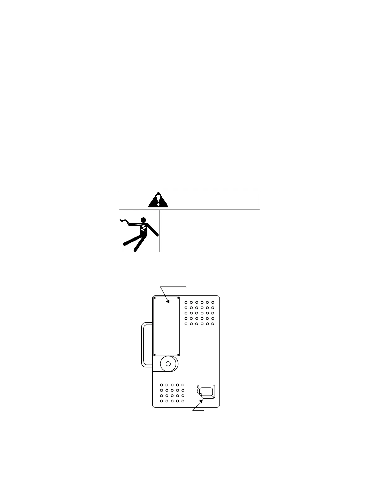
2. Loosen the PDS cable strain relief on the rear cover and rotate the strain relief plate to the open position,
Figure 5-1.
Accessory Cover Plate
PDS Strain
Relief Plate
Figure 5-1 MJ-X Control Panel Rear Cover.
3. Remove the six screws on the side of the rear cover that hold it to the control panel.
WARNING
120 volts on leads and inside control
panel housing.
May result in death or serious injury
from electric shock including equipment
damage.
Disconnect all power sources before
opening the control panel.
 Loading...


