MJ-4 Communications Module
17
1
1
6
9
5
13
14 25
Pin
Pin
1
1
2
2
3
3
4
4
5
5
6
6
7
7
8
8
20
9
22
*
*
*
Signal
Signal
Ground (Frame)
DCD
Txd
Txd
Rxd
Rxd
RTS
DTR
CTS
DSR
DSR
Ground (Signal)
Ground (Signal)
DCD
RTS
DTR
CTS
RI
RI
Shell (Frame Ground)
For Shielded Cable Connectors
Shell (Frame Ground)
DE9
DB25
Figure 7-7 RS-232 Connector Pinout
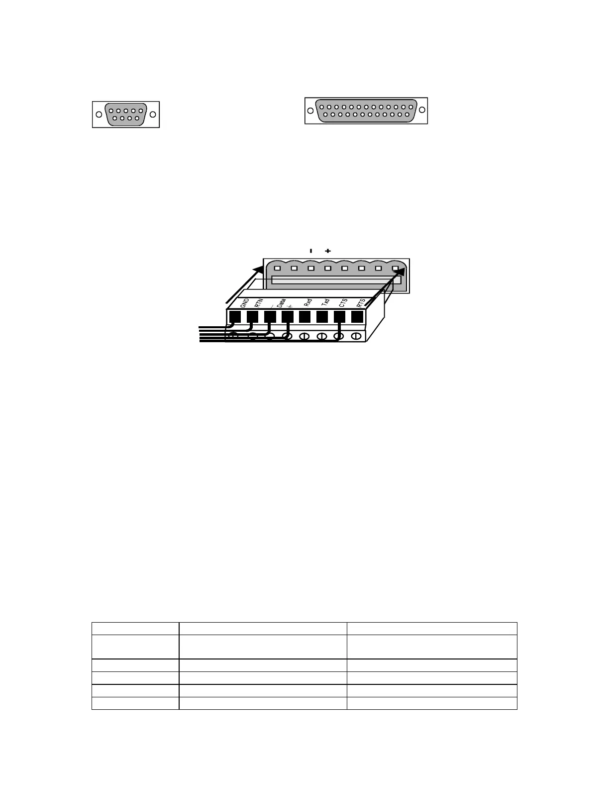
7.4 RS-232/485 Connections
The screw terminal block connector is keyed for proper insertion. Figure 7-8 shows the proper connector
orientation. Align the keys and insert the connector to interface to the RS-232/485 interface.
G
N
RTN
Da
ta
Rxd
Tx d
CT
S
RT
S
Figure 7-8 Screw Terminal Connection
7.5 Communications Module Configuration
Prior to using the MJ-4 Communications Module in the network, the communications module needs to be
configured properly for communications. The < COMMUNICATIONS > menu of the MJ-4 Control Panel provides
all the required communications configuration items for the communications module. Table 7-4 lists the
communications menu items in the order in which they appear on the MJ-4 Control Panel; default settings are in
bold.
1. Program the communications parameters of the MJ-4 Communications Module by pressing the Menu key twice
to display the < METER > menu.
2. Then press the left arrow key until the < COMMUNICATIONS > menu appears. Use the up and down arrow
keys to access the individual menu items.
3. To change the value of the parameter, press the Change key, and then use the arrow keys to toggle the choices
or set the value for the parameter. Press the Save key after changing the value of a menu item to enter the
changes, or press the Cancel Reset key to cancel the change.
Each time a configuration menu item is changed, the communications module is reset by the main MJ-4 Control
Panel. This reset is part of the process of updating the communications module with the new configuration.
Table 7-4 Communications Menu Items
Menu Item Description Selections
Data Stat =
XXXXX
Data Port status Not Applicable (This is a Status Item)
DatPortBaud Data Port baud (in bits/second)
300, 1200, 2400, 4800, 9600, 19200
Data Parity Data Port parity
None, Even
DataPortAddr Data Port address enable
OFF, ON
Reg Id Regulator Identification
0 - 32,766
 Loading...


