MJ-4 Communications Module
1
1 Introduction
This manual describes the installation and connection procedures for the MJ-4A
TM
& MJ-4B
TM
(here after referred
to collectively as MJ-4
TM
) Communications Module which has the Fiber Optic and the RS-232/485 interfaces
combined in one single printed circuit board. The operation and functionality of the Fiber Optic and the RS-232-
/485 interfaces are quite similar, only one of the interfaces can be used at a time. The manual covers the procedures
for connecting the module to a system of networked MJ-4 Tap Changer Control Panels.
1.1 Description
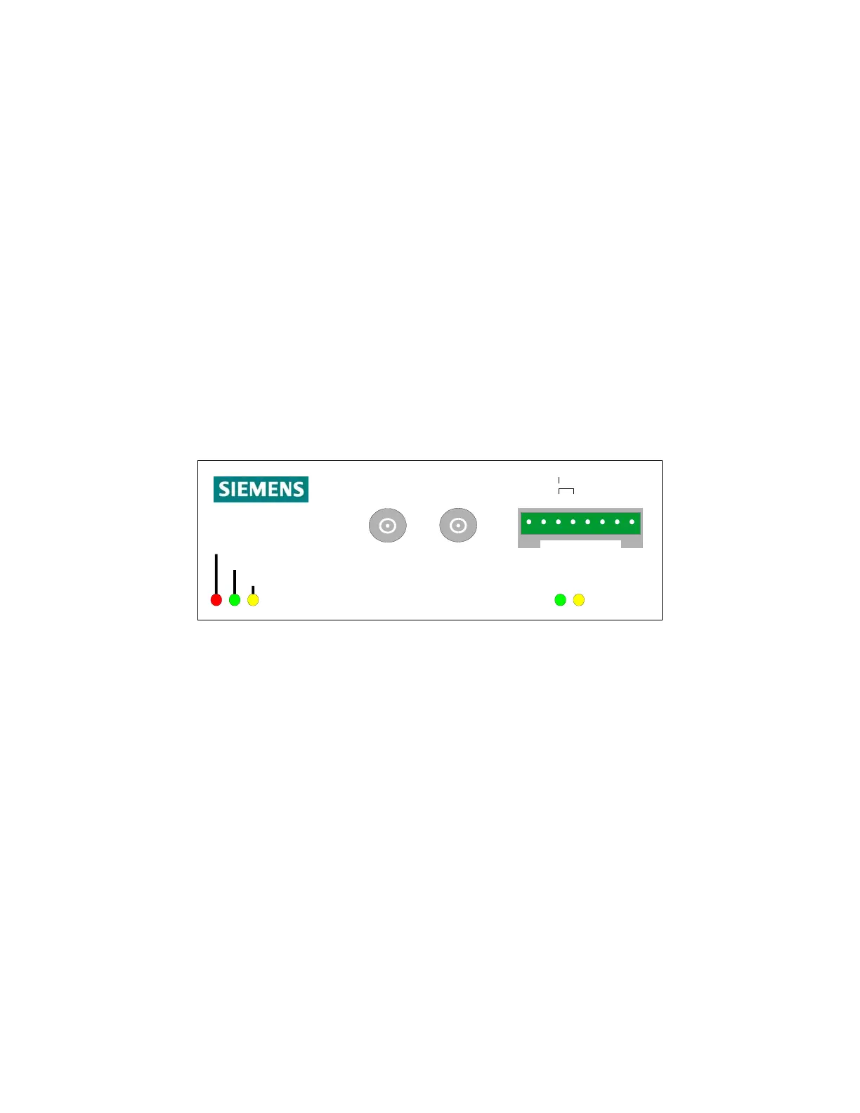
The Siemens MJ-4 Communications Module is the communication interface used to connect the MJ-4 Control Panel
to a network of regulator controllers, control devices, and supervisory equipment. Figure 1-1 illustrates the MJ4
Communications Module.
The fiber optic interface enables connection of the tap changer control panel to the supervisory equipment via
multimode fiber optic cable. The RS-232/485 interface enables connection of the tap changer control panel to the
supervisory equipment via electrical wire.
The MJ-4 Communications Module is installed in MJ-4 Tap Changer Control Panels. This allows you to easily
network the control panels and other field devices to a remote terminal unit (RTU) or other supervisory device. An
adapter kit is available for mounting MJ-4 Communications Modules in MJ-X Control Panels.
Rxd Txd
POWER
Watchdog
Communications
RS - 232 / 485
Communications Module
G
N
D
R
T
N
-+
R
x
d
T
x
d
C
T
S
R
T
S
Data
IN OUT
Figure 1-1 MJ-4 Communications Module.
1.2 LED Indicators
The MJ-4 Communications Module has five LED indicators.
• Power indicates the MJ-4 Communications Module is powered on.
• Watchdog when blinking steadily, indicates the MJ-4 Communications Module microprocessor and software
are functioning properly.
• Communications indicates communications activity with this module. (The Communications Module turns on
this indicator when it receives a valid message with a valid address.)
• Rxd indicates the communications module is receiving data.
• Txd indicates the communications module is transmitting data.
2 Transmission Methods
There are two transmission mediums available for sending data to the RTU:
• fiber optic
• wire
 Loading...


