MJ-4 Communications Module
9
4. Feed the PDS cable harness through the strain relief cutout while removing the rear cover.
5. Remove the accessory cover plate from the rear cover. Discard the accessory cover plate and mounting
hardware. If an Expansion Rack is installed in the accessory area, remove the rack and discard.
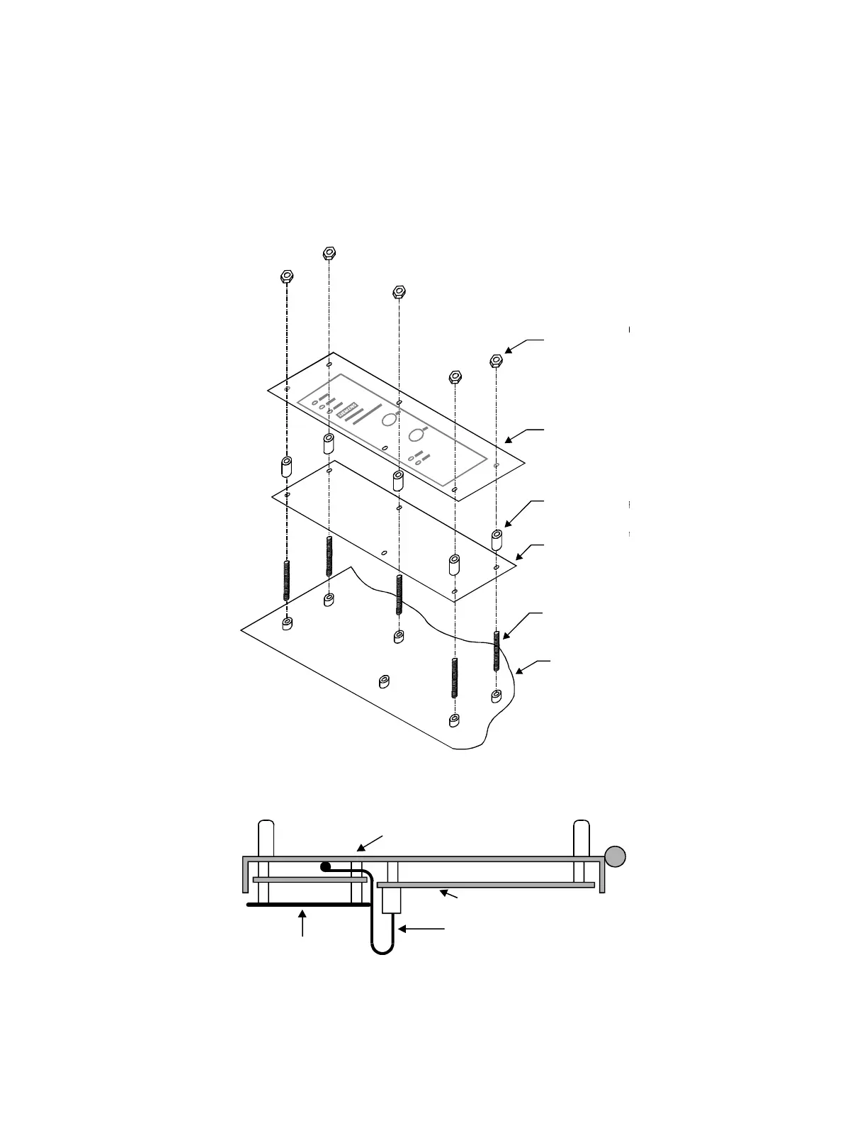
6. Mount the communications module printed circuit board to the MJ-X base with six 6-32 x 7/16” standoffs,
Figure 5-2. Ensure that the membrane switch cable is folded over itself and under the communications module
printed circuit board as shown in Figure 5-3.
6-32 x 3/8" Screw
6-32 x 7/16" Mal
e/Fe
Standoff (6)
PCB
Cover Pan
MJ-X Base
6-32x 3/8" Screw
6-32x 7/16" Male/
Standoff (6)
PCB
Cover Pan
MJ-X Base
Hexnuts (5)
Spacers(5)
PCB
Cover Pan
M
J
-
X
Ba
s
e
Threaded Studs(5)
Figure 5-2 Communications Module Installation in MJ-X.
MJ-X Control Panel
Processor Board
Communications
Module
Membrane Switch Cable
Figure 5-3 Membrane Switch Cable Routing (top down view).
 Loading...


