16
Table 7-2 lists the connections that must be made to connect the RS232/485 interface to a personal computer, RTU,
or other supervisory device. The MJ-4 Communications Module defaults to no-handshaking-required mode.
However, the communications module asserts RTS while it transmits data, but the module will ignore the CTS input
signal.
Table 7-2 RS-232 Intelligent Electronic Device Wiring
MJ-4 RS-232/485
Communications Interface
Personal computer, supervisory
device, or other network device
RTN Signal Ground
RXD TXD
TXD RXD
Table 7-3 lists the connections that must be made to connect the RS232/485 interface to a modem.
Table 7-3 Modem Wiring
MJ-4 RS-232/485
Communications Interface
Modem
RTN Signal Return
RXD RXD
TXD TXD
RTS RTS
CTS CTS
“RXD” is an input for Data Terminal Equipment (DTE) and an output for Data Communications Equipment (DCE).
“TXD” is an output for the DTE and an input for the DCE. Personal computer serial ports are configured as DTE
and the modems are configured as DCE. The communications module RS-232 connections implement DTE.
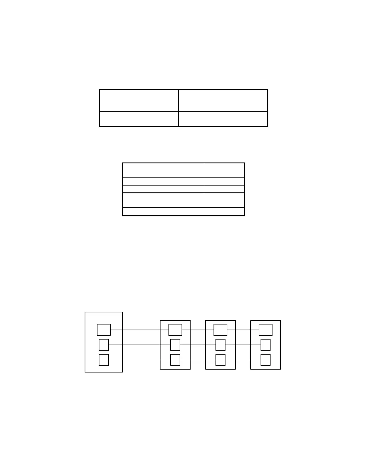
7.3.1 RS-232 Multi-drop Wiring
Multi-drop configurations require that the respective pins of the DTE devices be connected in parallel, Figure 7-6.
The standard pin assignments for RS-232 connectors are shown in Figure 7-7.
Note: For Figure 7-6, the RTU port is wired as “DTE”. When networking devices together, make sure the RTU
“data out” connects to the communications module Rxd, and the RTU “data in” connects to the communications
module Txd.
Signal
Return
Signal
Return
Signal
Return
Signal
Return
TX RX RX RX
RX TX TX TX
RTU MJ-4
MJ-4
MJ-4
Figure 7-6 RS-232 Multi-drop Configuration
 Loading...


