MOBILETT Plus HP SPR8-220.033.03 Page 8 of 12 Siemens-Elema AB
Rev. 02 10.02 SPS-UD Solna, Sweden
2 - 8 Installation and setting
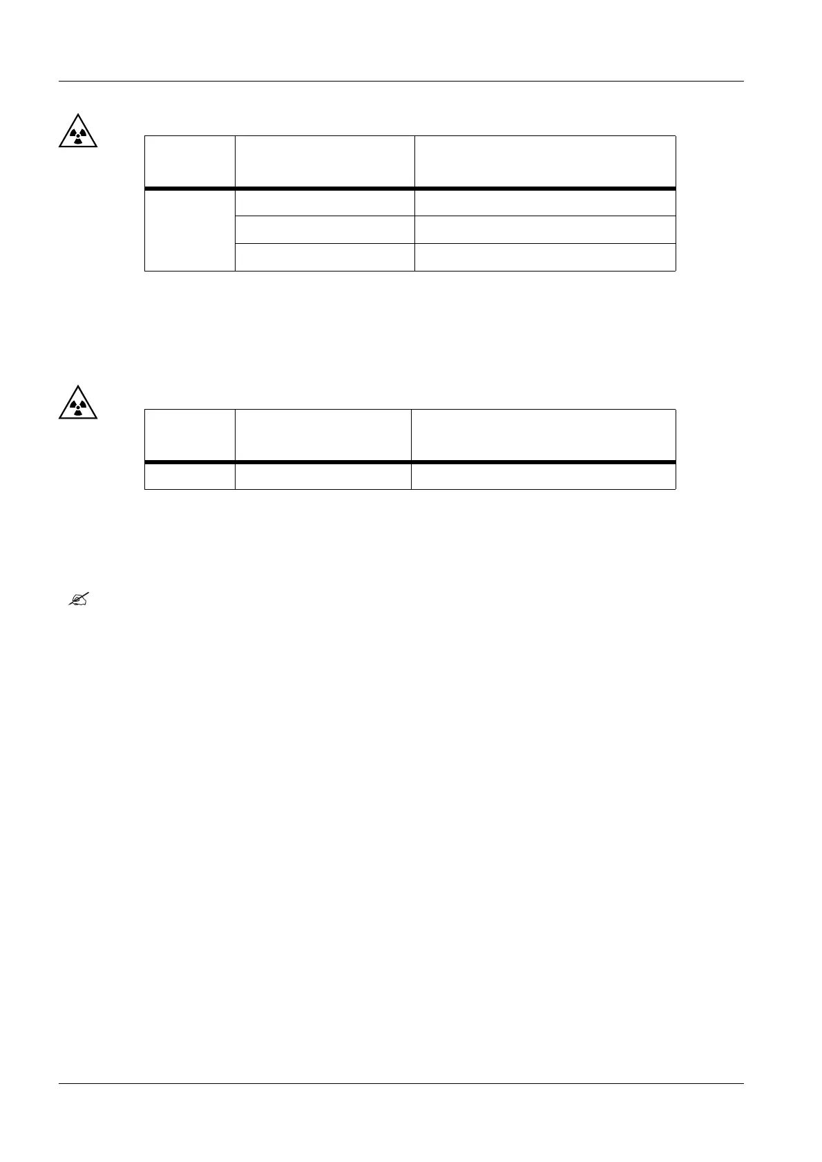
• Set the following exposure parameters and release exposure:
* The measurement inaccuracy of the respective measurement device must be subtracted
from these limit values.
• Connect the power supply plug and switch the main switch to position "M"
• Set the following exposure parameters and release exposure:
• Disconnect the power supply plug, roll up the cable and switch the main switch to
position "B".
Check the arm- and single tank movement 2
• Check the arm systems and the single tanks up and down movements. The arm and the
single tank should be easy to move and remain in desired positions. If this is not the
case, see "Service Instructions, section Adjusting the friction linings".
Adjustment, kV steps and upper kV / mAs limits 2
If the customer or local regulations asks for a limitation of the upper kV / mAs value, the
service program P14 and / or P15 have to be executed. Program P14 is also used to set
the kV steps to either 25 individual steps from 40 - 133 kV in whole exposure points, or 49
individual steps from 40 - 133 kV in half exposure points.
• Select Service Mode according to chapter "Capacitor formation".
• Select P14 (for kV steps and upper kV limit) or
Select P15 (for upper mAs limit).
• Press lamp button to display actual kV limit / mAs limit.
• Press kV / mAs +/- button to change value.
• Press lamp button to store value and leave program.
• Switch "1" of S1 on D1 to "OFF".
• Check the chosen values.
kV Meter
selection
Exposure parameter Limit values* to be maintained
DC voltage
52 kV 50 mAs 49.0 - 55.0 kV
81 kV 20 mAs 77.0 - 85.0 kV
133 kV 12.5 mAs 126.4 - 139.6 kV
kV Meter
selection
Exposure parameter Limit values* to be maintained
DC voltage 81 kV 20 mAs 77.0 - 85.0 kV
 Loading...