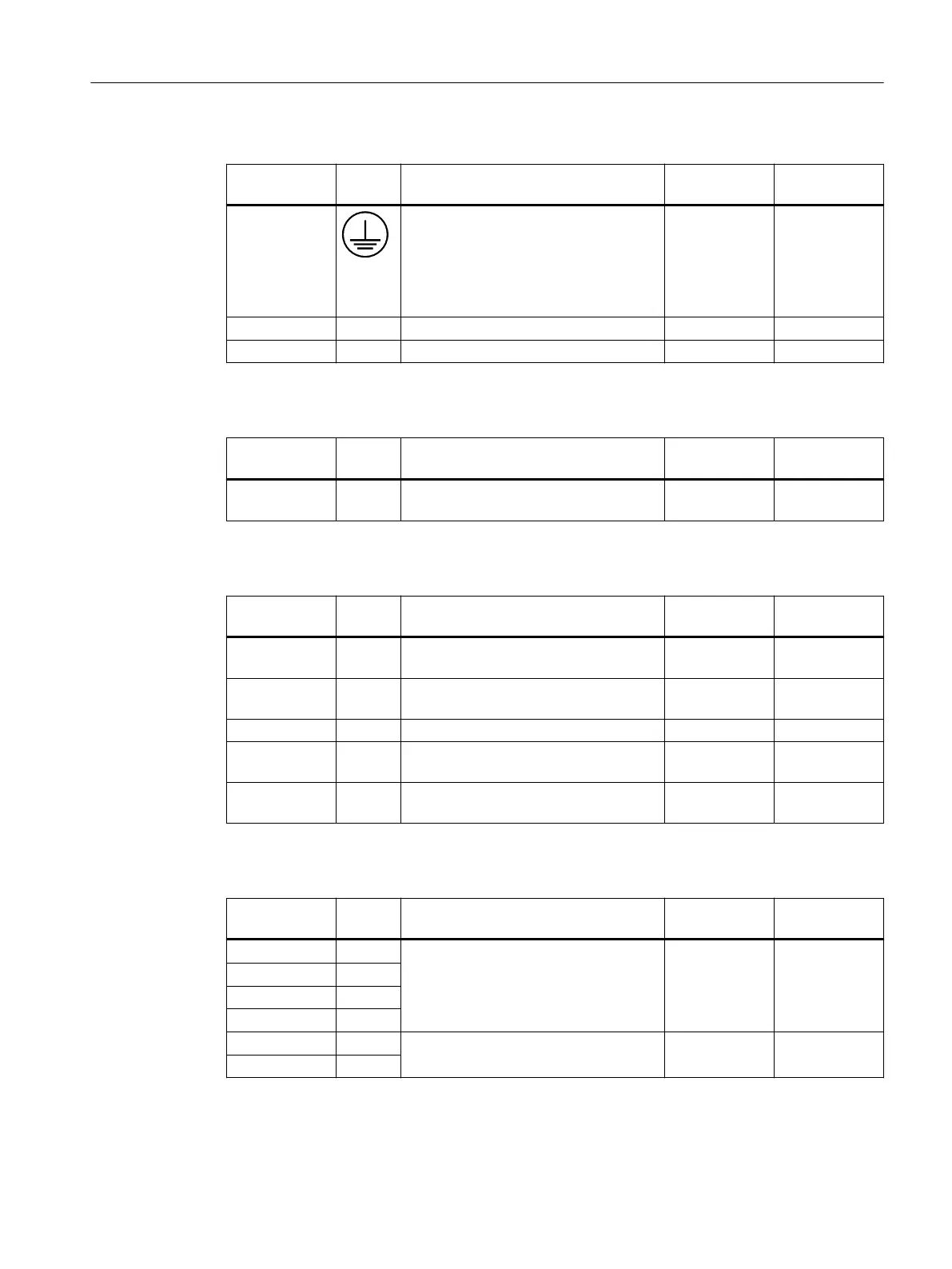
Table 3-3 Control panel
Position num‐
ber
Inter‐
face
Designation Max. cable
length
Type
⑧ Protective conductor connection Length and
cross section in
accordance
with the na‐
tional regula‐
tions
Threaded bolt
M5
⑬ S13 Emergency stop button
⑭ S11 Emergency stop override
Table 3-4 Connection board
Position num‐
ber
Inter‐
face
Designation Max. cable
length
Type
⑰ X1 24 V power supply interface 10 m Terminal block,
3-pin
Table 3-5 COM board
Position num‐
ber
Inter‐
face
Designation Max. cable
length
Type
⑨ X60 /
X61
Connections for two handwheels (TTL /
dierential - can be set with switch S1)
5 m 15-pin D-sub
male connector
⑩ X20 /
X21
Ethernet ports 1 and 2 100 m RJ45
⑪ X70 Direct keys
⑯ X30 Interface for feedrate override rotary
switch
0.6 m 10-pin male
connector
⑱ X31 Interface for spindle override rotary
switch
0.6 m 10-pin male
connector
Table 3-6 User keys
Position num‐
ber
Inter‐
face
Designation Max. cable
length
Type
⑲ X20 Individual wiring 100 m RJ45
⑳ X21
① X22
② X23
③ X24 Extension 100 m RJ45
④ X25
Description
3.4 Interfaces
Machine Pushbutton Panel: MPP 464 IE H
Equipment Manual, 03/2021, A5E50810237B AA 23
 Loading...