Connecting
6
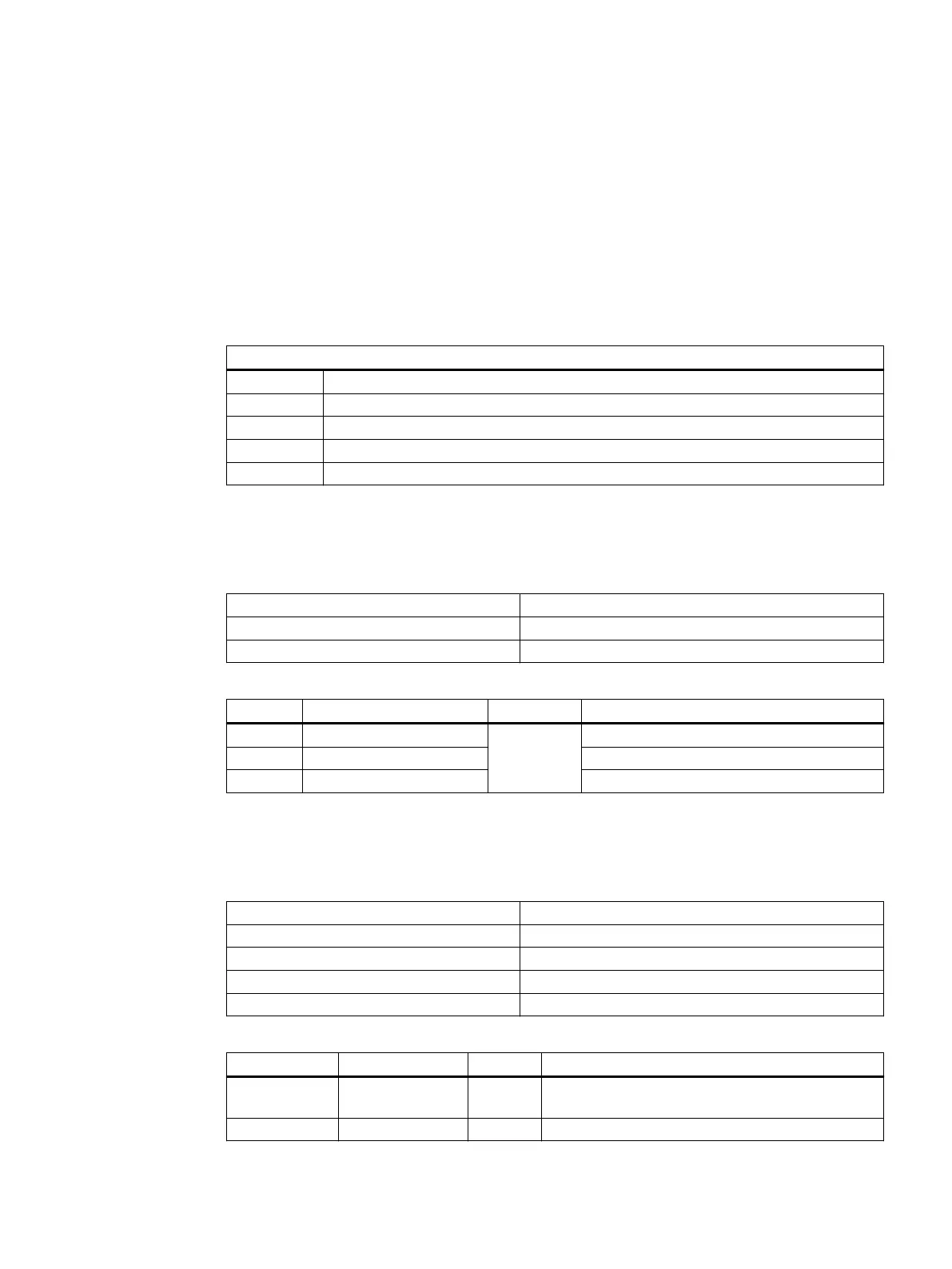
6.1 Pin assignment of the interfaces
The pins of the component interfaces are assigned as specied in the tables below. Any
deviations are indicated at the relevant point.
Signal type
I Input
O Output
B Bidirectional (inputs/outputs)
V Power supply
- Ground (reference potential) or N.C. (not connected)
6.1.1 Power supply
Connector designation: X1
Connector type: Terminal block, 3-pin male connector
Total cable length: 30 m
Pin Name Type Meaning
1 P24 (+) V/V/- 24 VDC potential (20.4 to 28.8 VDC)
2 M24 (-) 0 V
3 Functional grounding Connection for grounding the housing
6.1.2 Ethernet ports X20, X21
Connector designation: X20, X21
Connector type: Standard RJ45 socket
Max. data transmission rate: 10/100 Mbit/s
Max. cable length: 100 m
Connector assignment: Downlink (switch)
Pin Name Type Remark
1 RX+
I Receive +
2 RX- I Receive -
Machine Pushbutton Panel: MPP 464 IE H
Equipment Manual, 03/2021, A5E50810237B AA 45
 Loading...