Placement locations
The following gure shows all placement locations that are possible, occupied by default, and
optional.
#1#1#1#1#1#1#1#1
#1#1#1#1#1#1#1#1#1
#1#1#1#1#1
#1
#1
#1
* Optional placement location
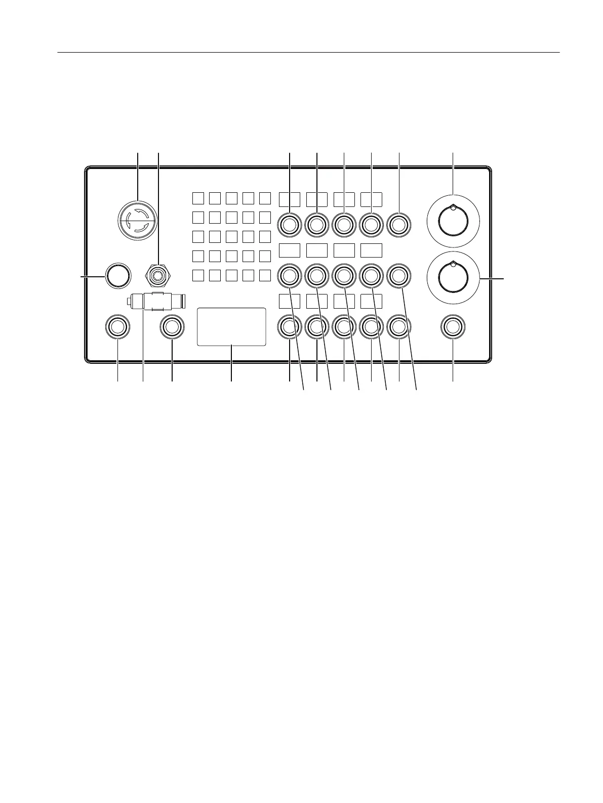
Figure 4-2 Placement locations
Connectable operator controls
Inputs for:
• 25 function keys
• 18 long-stroke keys (max.)
• 2 rotary selector switches
Outputs for:
• 47 LEDs (14 led to plug connector)
Actuating elements
The states of the actuating elements S1 to S4 and S7 to S10 are transmitted to the control system.
They also have electrically isolated contacts (common roots) for user-specic wiring.
Command devices can be connected at the following locations according to the table in the
chapter "Accessories and spare parts" > "Displays and operator controls":
• S1 to S4
• S7 to S10
Operator control and display elements
4.2 Front face
Machine Pushbutton Panel: MPP 464 IE H
Equipment Manual, 03/2021, A5E50810237B AA 37
 Loading...