Assembled PCB handheld unit connection
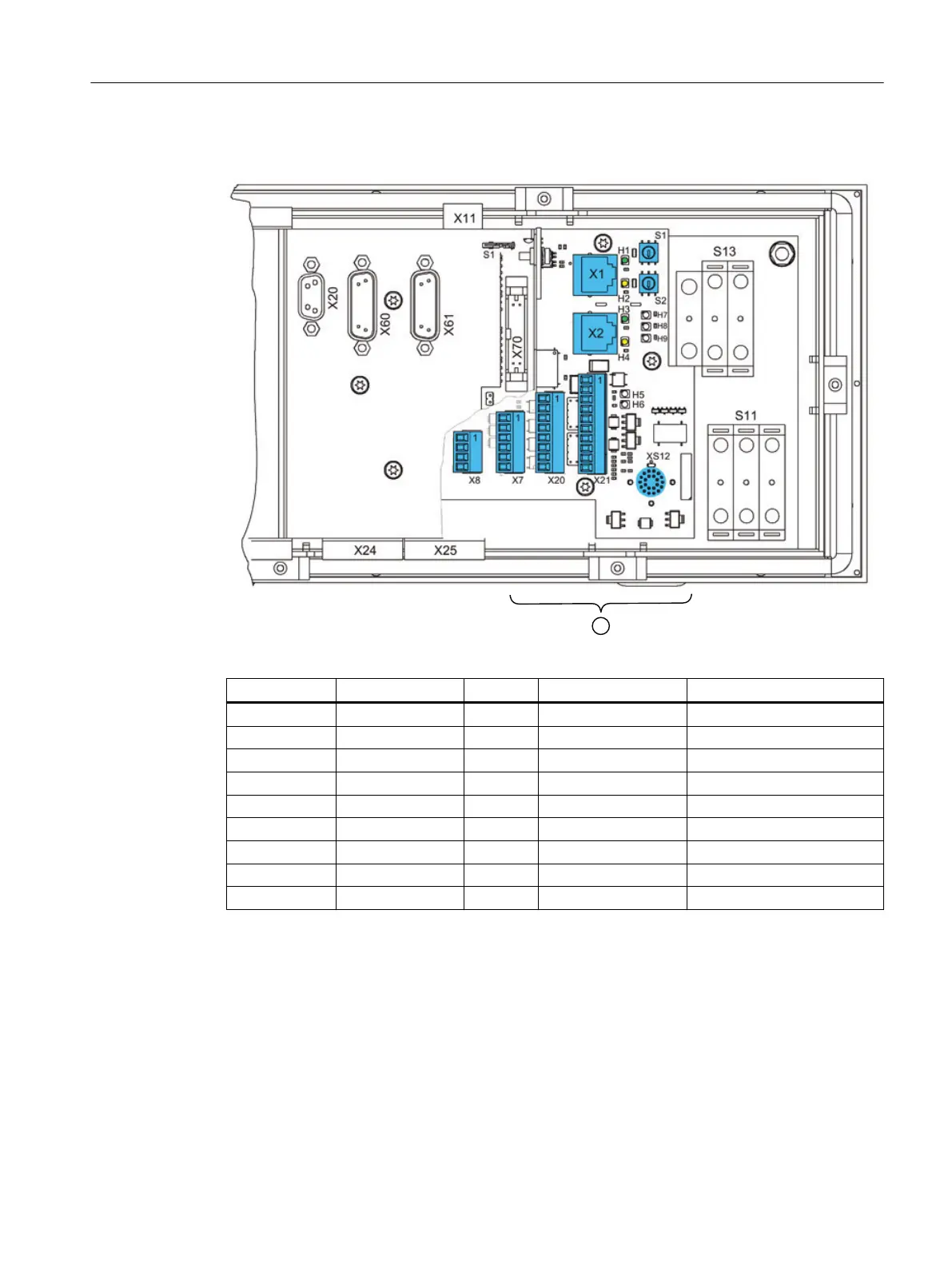
Figure 4-3 Rear MPP 464 IE H with LEDs on HGA board HT 8 ①
LED Color for Meaning
LED1 (H1) LNK Green X1 RJ45 Connection established
LED2 (H2) ACT Yellow X1 RJ45 Transmission active
LED3 (H3) LNK Green X2 RJ45 Connection established
LED4 (H4) ACT Yellow X2 RJ45 Transmission active
LED5 (H5) LNK Green HT 8 transmission
LED6 (H6) ACT Yellow HT 8 transmission
LED7 (H7) Power OK Green
LED8 (H8) FAULT STAT1 Red Error
LED9 (H9) FAULT STAT2 Red Error
Operator control and display elements
4.3 Rear side
Machine Pushbutton Panel: MPP 464 IE H
Equipment Manual, 03/2021, A5E50810237B AA 39
 Loading...