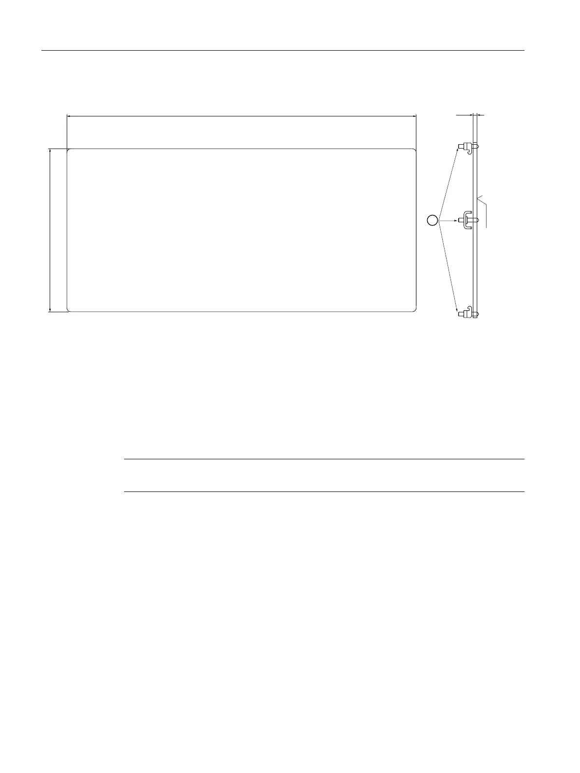
Panel cutout
3[
① Tension jack with threaded pins
*) Rz within the device dimensions
Figure 5-2 Panel cutout MPP 464 IE H
• Corner radius R5 or chamfer 5x45°
• Sealing area circumferential 7+1 mm
Tension jacks
The MPP 464 IE H is attached to the rear of the operator panel using 8 clamps (included in the
scope of supply). The tightening torque is 0.4 Nm.
Note
The distance to the next MPP all around must be at least 1 mm.
Mounting position
The mounting position is max. 60° to the vertical.
For mounting positions greater than 60°, a fan must also be installed to keep the ambient
temperature of the machine control panel constantly below 55 °C.
Mounting
Machine Pushbutton Panel: MPP 464 IE H
42 Equipment Manual, 03/2021, A5E50810237B AA
 Loading...