English
Additional Equipment Manual EEx p E-9
Order No.:
A5E 000 58873-02
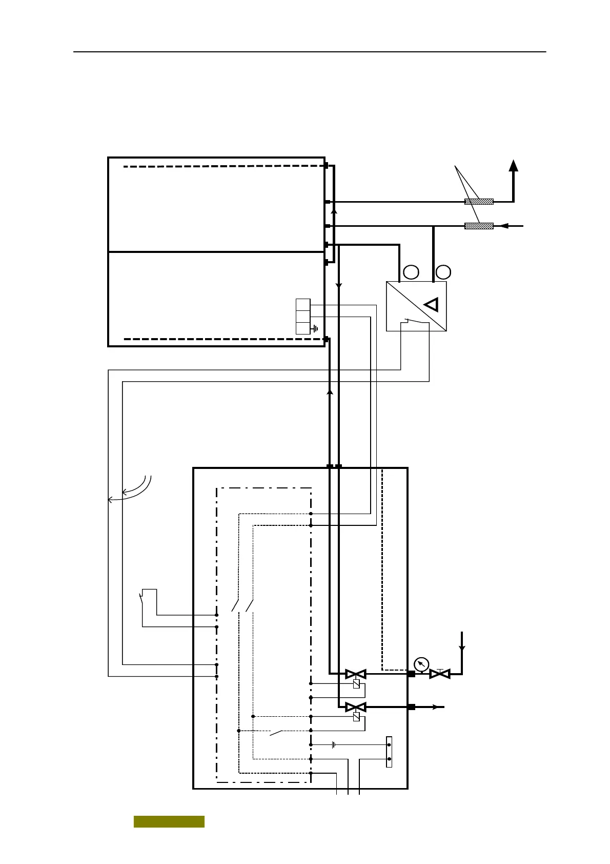
3.2 Assembly diagram for the versions EEx p with "Compensation of losses
resulting from leaks"
PE L
N
Power supply
connection
Outlet
valve
Inlet valve
p
EEx p purging gas monitoring device
L1
N
PE
Outlet of
purging gas
into Ex-free
zone
-
Sample
gas inlet
Sample
gas outlet
Intrinsically-safe
scanning of
pressure switch
Inlet of protective gas
(purging gas)
input pressure: 0,2...0,4 MPa
CALOMAT 6F
OXYMAT 6F
ULTRAMAT 6F
Control electronics
Purging gas
pipelines:
max. 4 m long;
diameter > 8 mm
*
)
*) With resistor for monitoring line breakages if applicable (see Instruction Manual of EEx p purging gas
monitoring device). If the sample gas cannot be applied with operational reliability, a second differential
pressure switch must be connected whose contact must be connected in series with the first switch.
With certain suppliers of EEx p purging gas monitoring devices, a relative pressure sensor can also be
connected instead of the differential pressure switch.
Gas connections:
C 6F and O 6F: 2 and 4
U 6F (SG): 1 and 2
U 6F (RG): 3 and 4
(see also associated
manual)
5
6
7
8
Flame inhibitors
Differential
pressure
switch
V1
Key switch
(only with
occasionally
combustible
gas
mixtures)
+
 Loading...